CNC Router Plans and Construction
The following is a construction log of the CNC router I designed and built in 2025. Included in this log are the plans and construction details one would need to build their own. You will need a CNC to make some of these parts to the necessary accuracy, and in these cases CAD files or detailed drawings are provided. So if you know someone with a CNC, then you can make a CNC!
This is ongoing project, so if it seems to be incomplete then check back later. We will get there together!
CNC Axes
This CNC is a gantry style CNC router. A Gantry (the bridge-like structure) rides along the edges of the table on rails. The gantry supports a Carriage, which is the plate that rides along the front of the gantry and has the stuff to move a tool up and down. The Tool is the router, laser, or plasma cutter. So there are three axes (XYZ):
- X - The Table axis
- Y - The Gantry axis
- Z - The Tool axis
If you want, the X and Y can be Y and X, your choice. And if you add a rotary tube cutter, this is typically the A-axis.
Worktable
One of the major advatanges to this design is that the CNC table is available as a worktable. That is the origin of the name of the company: Worktable CNC! Unless you use it everyday, workshop floor-space is too valuable to have an area dedicated to an CNC just sitting there wasting space.
With this design, the CNC table is your shop worktable:
- The gantry is parked at one end.
- There are no side rails to work over.
- The table is strong and very flat.
- There is a spoil board on top of the table which you can mark on, spill glue on, drill in to, burn... and you can mill it flat again.
It is not just a CNC, it is your Worktable CNC!
(Sorry, I could not help myself)
OH NO! A Plywood CNC!
A common first reaction to a plywood structure is Oh No! That is probably really flexible! Do not use plywood! This is an honest reaction. Wood is not as strong as metal. However, there is a lot more wood in this box-beam gantry than the quantity of metal you might see in an Erector Set type gantry.
Respectfully, there are a lot of bolt-together metal CNC designs that just do not get it right. They make it very strong in one dimension (giving the appearance of a strong system) but do not account for all of the actual loads. The gantry is not just a bridge across the table, it must resist the bending and twisting loads from the tool. Many flat gantry style designs do not account for this. A box-beam does. Plus, the biggest deflection might be from the drive system. A four foot rubber cog belt or a direct drive stepper motor are bad choices!
Please read this: CNC BASICS
And this: CNC SPEED, RESOLUTION, AND ACCURACY
Obviously this design is not equal to a commercial, welded-steel box-beam, servo-driven, two-ton gantry CNC. It is however stronger, more accurate, and more stable than many (most) DIY designs out there. I have been using a plywood CNC for years:
- My table has a cutting area of greater than 4 feet x 14 feet.
- I can drill a 3/32 inch hole, travel the table, and easily put the drill back in the same hole.
- I can get 0.2 mm (0.008 inch) accuracy with a finishing pass.
- My CNC is made from plywood: Making another is no more difficult than making a cabinet.
Units of Measure
This CNC was designed and built in the USA. Normally this would mean US Customary units (feet and inches). However, almost all of the components ad materials used are sourced from the rest of the world, meaning that they are built using Metric units. So, to make things simple...
The default unit of measure for these CNC Plans is the Metric System.
A couple of items that use US Customary (some bolts, V-groove bearings, steel angle, etc.). Those I will note their size in inches. Otherwise, I will describe things in millimeters.
To my friends in the USA:
I have had a career as an engineer and have used both systems extensively. It is not a political thing and I am not trying to be defiant: A measurement system is just a tool. Metric is easier. The math is easier. Almost everything in our lives was designed in Metric to even Metric units. It just makes sense.
And one little suggestion if you decide to use Metric: Centimeters is for measuring the length of your arm, the depth of the snow, or the size of the fish that got away. It is not for formal design and manufacturing. It implies an accuracy of about the thickness of your finger. It is an informal unit, and pervasively used by we in the USA because it is close to the inch. For formal design: use millimeters. It is good practice to stick to the units that look like this:
1,000,000,000
1,000,000
1,000
1
0.001
0.000001
0.000000001
Giga, Mega, Kilo, one, milli, micro, nano. The units at the commas (every three zeros). Centi is not one of them.
(OK, rant over)
Design
When I was an apprentice, the senior engineers that taught me how to design were the ones that spent a career using a drafting board and drawing by hand. There was an art to it all. Proper drawing arrangement, the even use of white-space, and neatness were highly important in clearly conveying design information. We were essentially creating deliverables that only physically existed as pieces of paper. Those papers reflected your craft.
Because of this initial training, my favorite way of conveying 3D design information is the good old 2D projected three-view. But I also work in a world where 3D parametric solid modeling is now the standard for component design. No big deal, I can do that too.
From experience, if you are making one-off items out of flat panel materials (a special cabinet, a jig, a worktable, etc.) then it is much faster to draft that in 2D, copy-paste the part outlines to a nested cutting layout, and generate GCodes from that sketch. There is no sense to draw this stuff in 3D because you have to break it back down to 2D arrangements anyway.
3D solid modeling is necessary if the assembly is complex (and you can not otherwise visualize part relationships), or you will make the same thing but in different sizes (this is where parametric shines), or the output file needs to be in 3D (such as with CNC profiling or 3D printing).
With all of the above said, I normally design my CNC routers in 2D. And I am suggesting that you design in 2D as well. Too often I have seen very simple things drawn in 3D. If the goal is to make the thing, do not waste extra time drawing it.
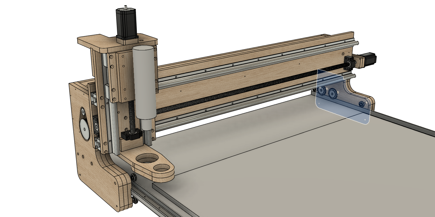
The structure of this CNC is not that complex. In an effort to better convey the design on this web page, I have designed in both 3D (to give you the pictures below) and 2D (to actually make the thing).
Here is some images of the 3D model:
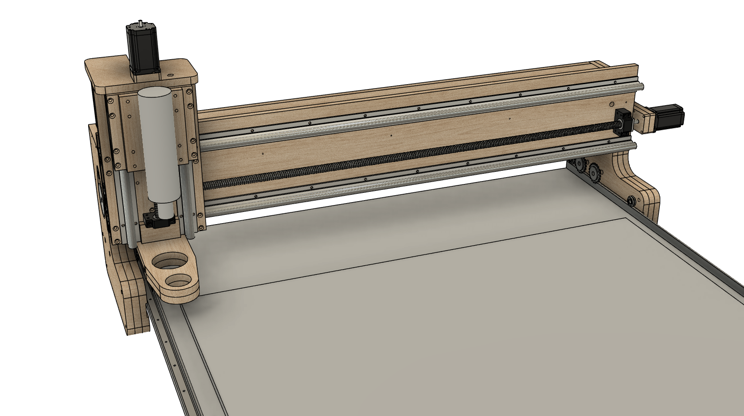
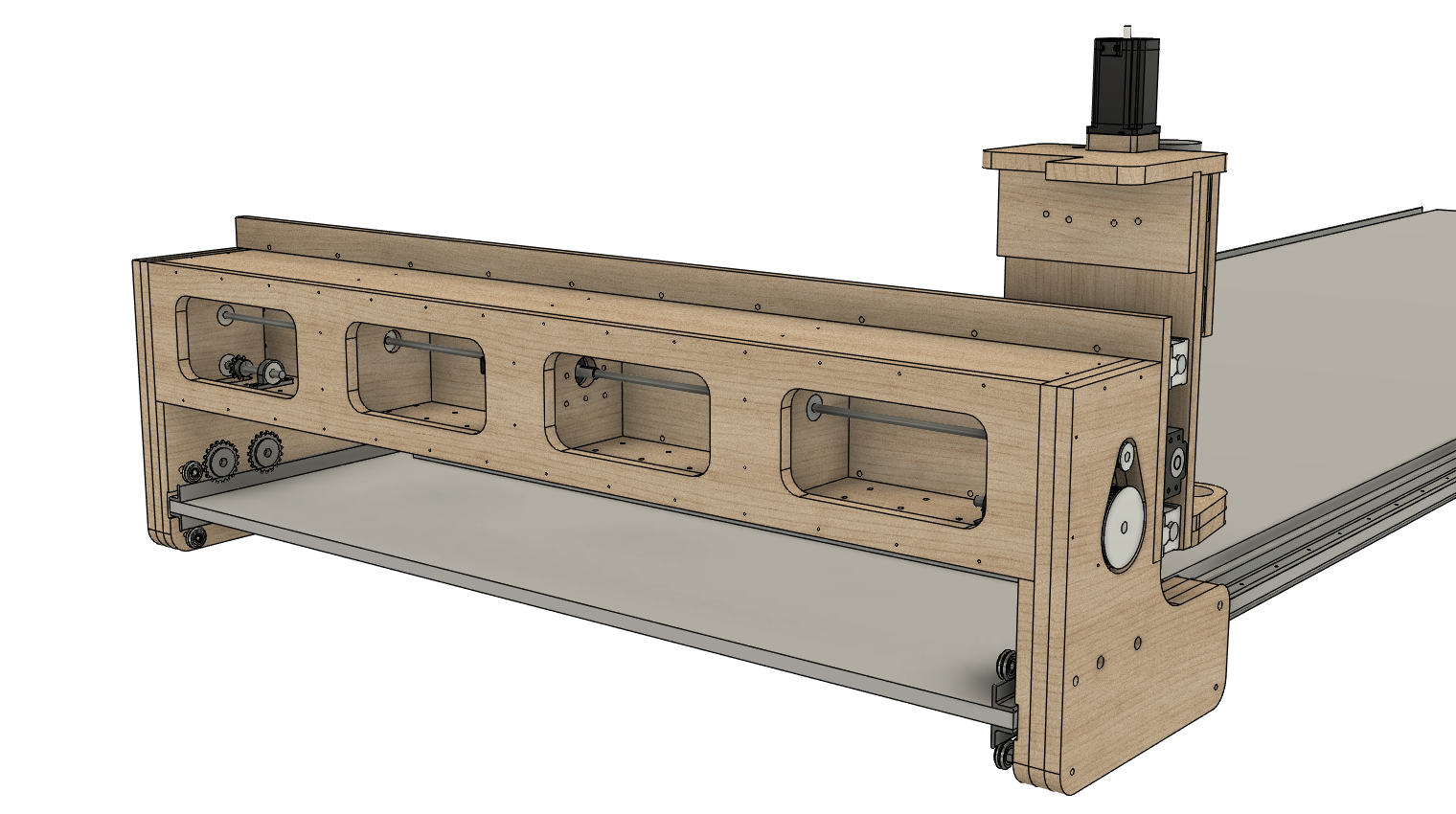
At this point, I could have continued in the 3D CAD/CAM package to create the final GCode files. However, I proceeded in a somewhat unusual fashion and used the 3D model to create 2D drawings. Crazy, right?!
Table Design
For starters, here are the free table plans:
On to the design...
The width of the table (the Y or gantry axis) is determined by the width of the CNC gantry. The CNC gantry is 1,500 mm in total width (with 1,270 mm of travel) and this is based on common linear slide lengths. The gantry construction and final roller locations then constrain the table width. You can get an idea of this from the images above. The final width of the table is 1,390 mm.
The cool thing about this design is that the table length (the X or table axis) can be as long as you need it. However, with the table width being wider than four feet, you have to rotate a 4 x 8 foot sheet of plywood and cut the width from the eight foot side of the sheet. This results in a table length of only four feet. So to make a long table, you have to connect a bunch of four foot table sections.
For international compatibility (and the fact that I like round numbers), I designed the table length on integrals of 1,200 mm length sections (yep, just less than four foot). This also gives me an opportunity to perfectly trim the plywood edges, since sometimes the factory edge is not exact.
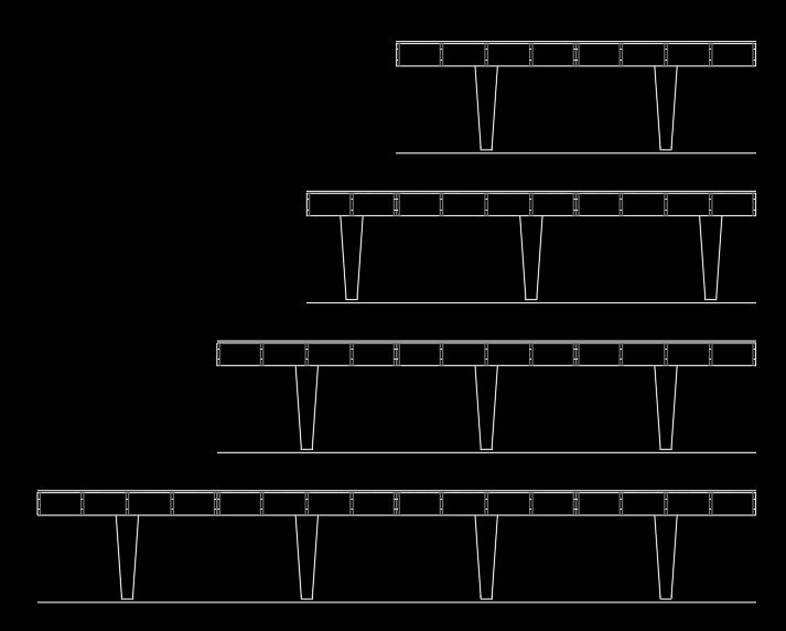
Here are some table length options:
-
2,400 mm : Two sections. A nice little table but not long enough to cut 4 x 8 sheet stock.
-
3,000 mm : The minimal length to cut 4 x 8 foot sheet stock.
-
3,600 mm : Three sections.
-
4,800 mm : Four sections. My favorite. Long enough to cut 4 x 12 foot sheet stock, cut 12 foot tubing, build an aircraft wing, and cut 4 x 8 foot stock with room at the end to build.
The side view of the four choices are in the image below:
One very impractical length is:
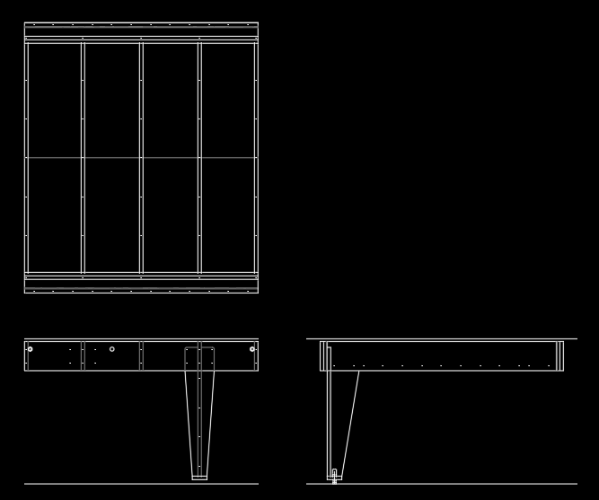
- 1,200 mm : One section. You only have about 800 mm of cutting length, but it is a nice little table if you are really limited on space and only plan on cutting, etching, or engraving small stuff.
What the hell, let's build this one!
This table will be 1,390 mm (Y or gantry axis) x 1,200 mm (X or table axis). You can see in the image I have drawn the side of the table, and then projected that into the three views:
With these three-views, I can quickly cut-paste out the geometry to create part outlines. These are shown below nested onto how they might be cut from the 4 x 8 foot plywood:
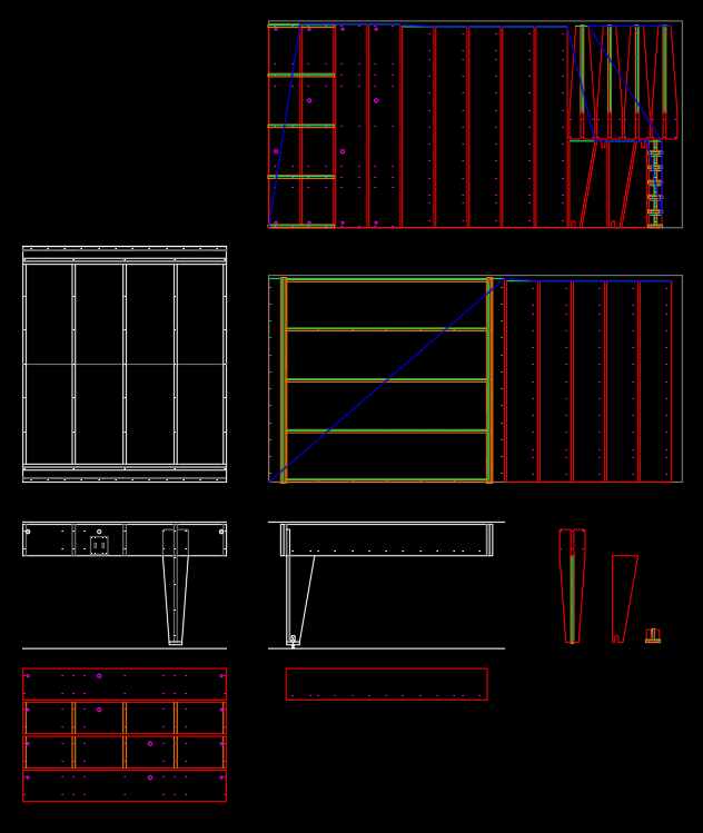
Again, just stop here when designing for yourself. If you are making a thing there is no need to waste time going beyond this sketch.
Gantry Design
For starters, here are the free CNC plans:
This is still a work in progress. When finished and all details are verified, I will post the complete CAD file here.
To make an accurate CNC, you have manage the engineering trade-offs: If you design a lot of clearance under the gantry, you increase the leverage the reacting cutting force has increasing the twisting of the gantry (this decreases accuracy). If you want a really fast CNC you lower (or omit) the gearing of the motors resulting in a loss of resolution and a decrease in final torque (both decrease accuracy). So:
-
The gantry is just tall enough to mill 2 inch foam plus a little clearance for safety.
-
The motors are geared down as much as possible while maintaining moderate top speed.
-
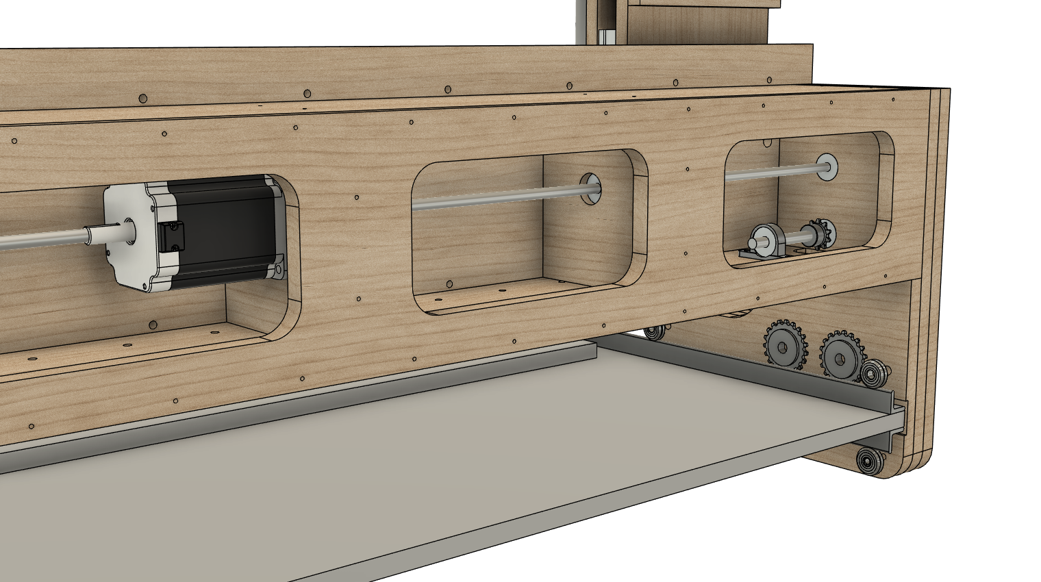
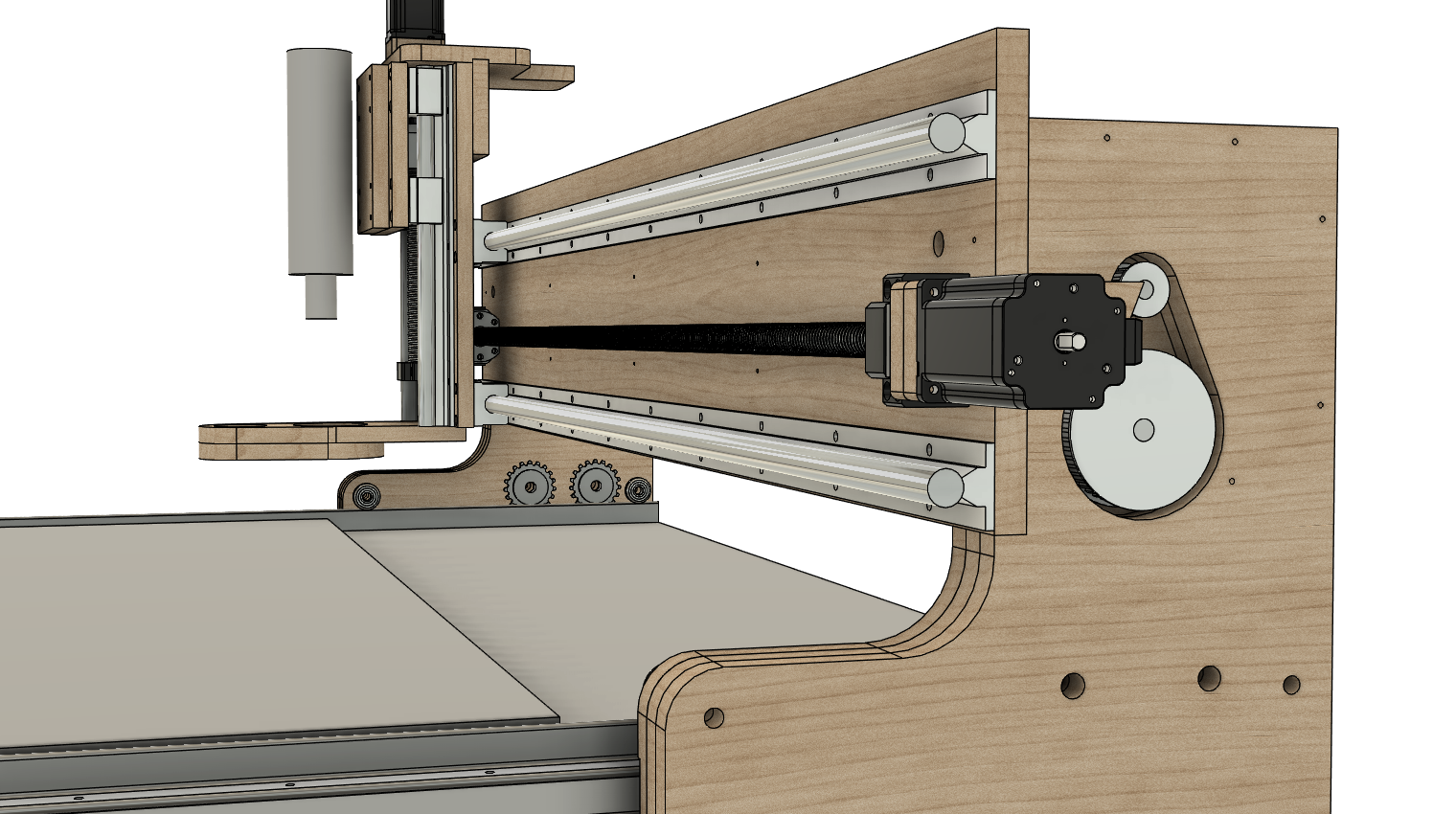
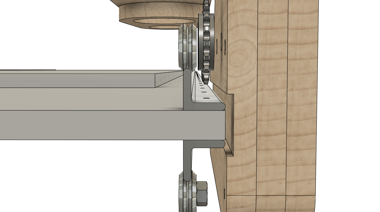
The gantry moves across the table using a chain drive (simple, inexpensive, available in really long lengths, and accurate enough).
-
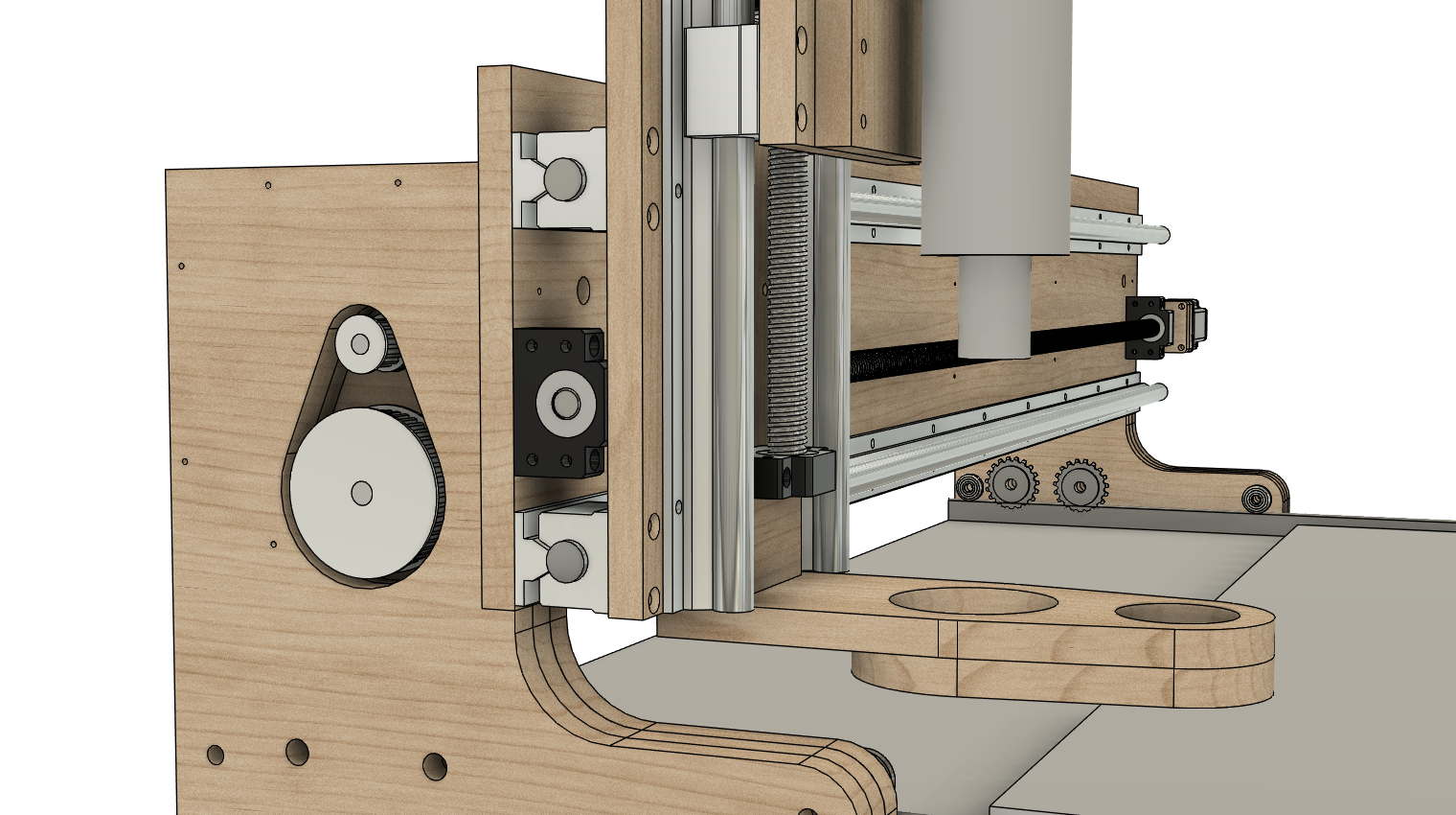
The head moves across the gantry using a ball screw. This is located as low as possible to position it nearest to the reacting cutting forces (this drive should definitely not be located on the top of the gantry which seems to be popular in other designs). The pitch of this screw is as fine as possible while maintaining a moderate top speed.
-
The tool moves up the head using a finer pitch ball screw. This selection is one where the tool will not free-wheel down once the power is turned off.
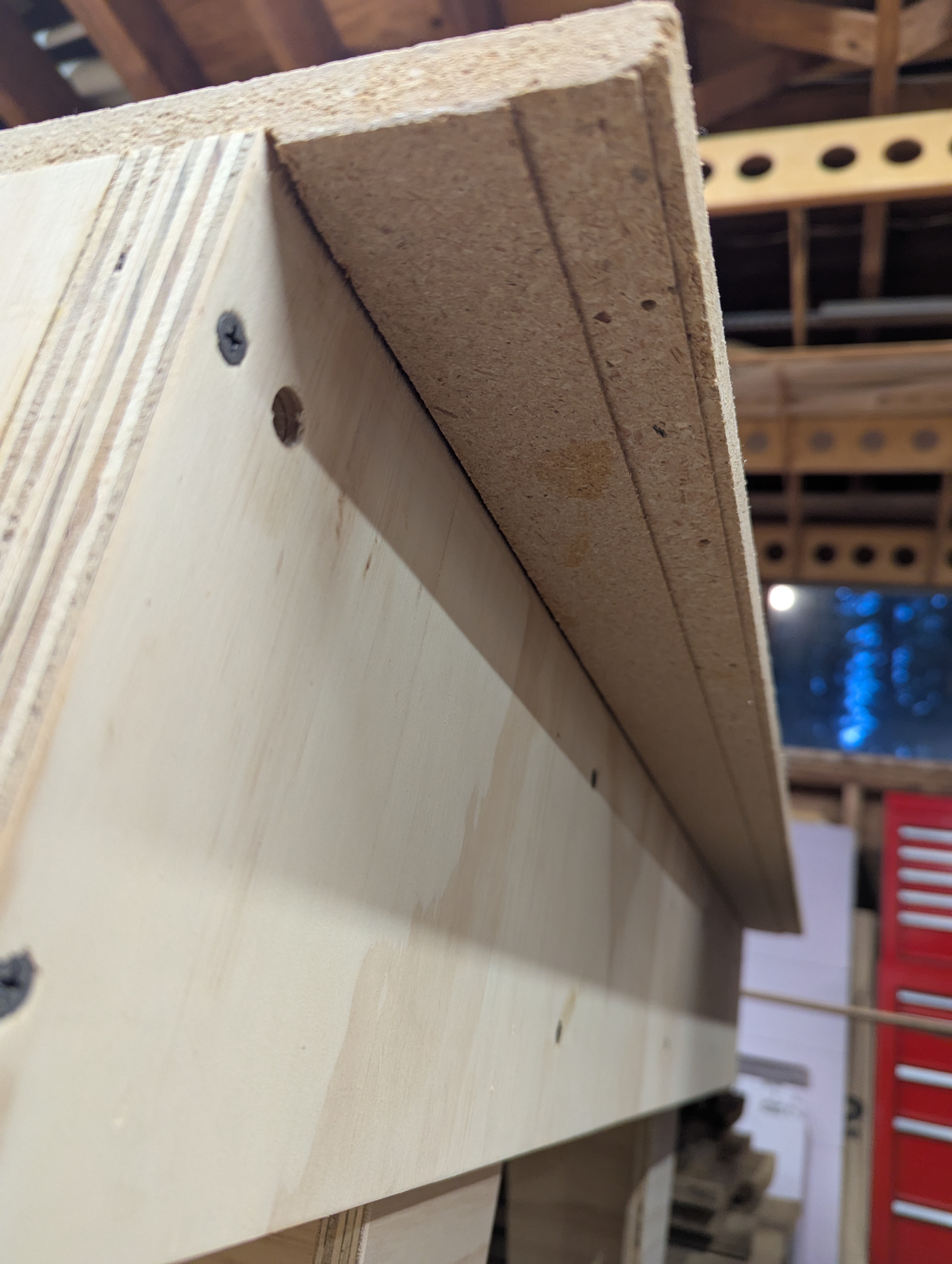
The gantry is a box-beam (a long skinny box with inner ribs providing structure) and it is supported by thick side plates. The gantry structure is made from 18 mm thick, 13 layer, Baltic Birch cabinet grade plywood. Do not use particleboard or MDF. There is economy plywood available, as long as it is 18 mm thick.
If you choose to use plywood specified in inches, it will not match the CAD files. Additionally, inch plywood is typically inconsistent in thickness from batch to batch. So you will have to measure the thickness of the plywood you get and revised every part in the design to coordinate. (This is why I use plywood specified in Metric. When they label it 18 mm it is very consistently 18 mm).
The remaining details of the gantry design are noted in the construction sections below.
Building the Table
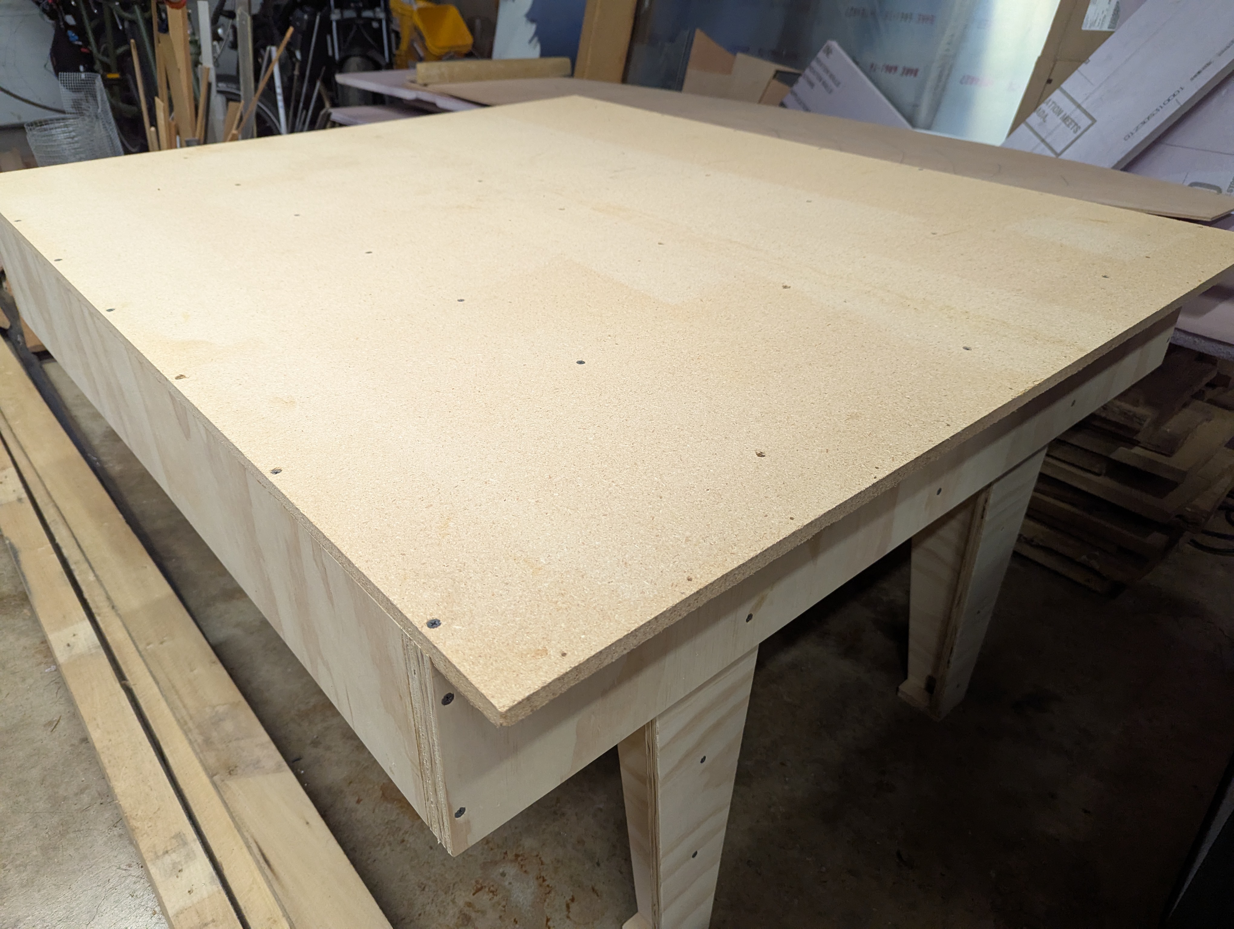
The plans call for 18 mm plywood for everything. But since I had an extra sheet of particleboard from a previous project, I used that for the top. As shown in the plans above:
- The Stringers (Sides/Longitudinals) are two pieces laminated.
- The Joists (Centers/Laterals) are spaced 300 mm on center.
- The stringers are dadoed to receive the joists.
- The top is dadoed to fit down onto the stringers and joists.
- The legs are similar in construction.
- All held together with drywall/construction screws and wood glue.
It is basically just a table. Very accurate and sturdy, but just a table:

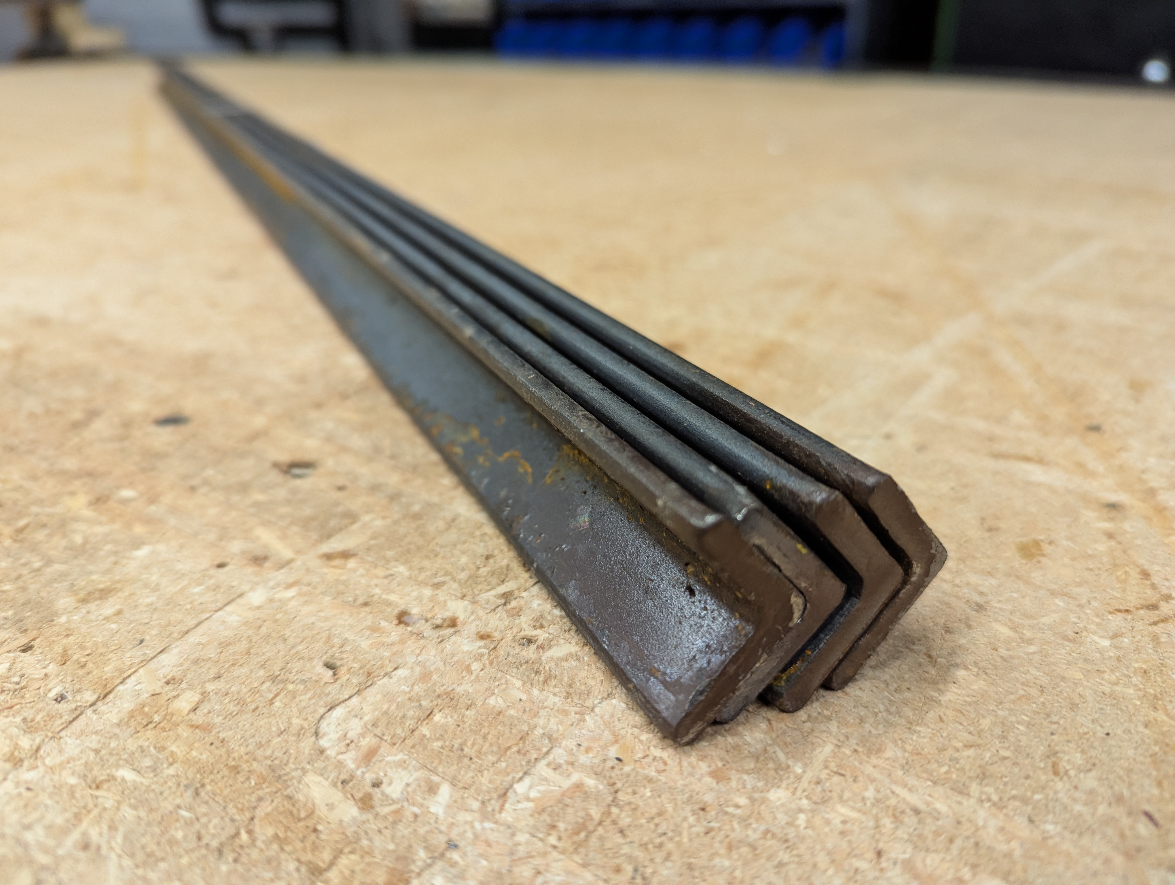
Steel Angle Rails
The gantry travels along linear rails which are steel angles. These are 1 x 1 x 3/16 inch and as long as the table. These are typically available in 20 foot lengths. I always just get several full length pieces to avoid the supplier from bending them during handling...
It is very important to make sure this steel angle has not been bent! Not even a little bit.
When you purchase these, do not let anybody just grab one piece in the middle and pick it up. Usually these are delivered to the steel supplier in a massive bundle and are put on a shelf all tied together. Start there. Pick out four pieces on that shelf and before anyone picks them up, immediately wire tie them into a tightly nested group. Then, get several people spaced out to carry them. Do not let them get bent.
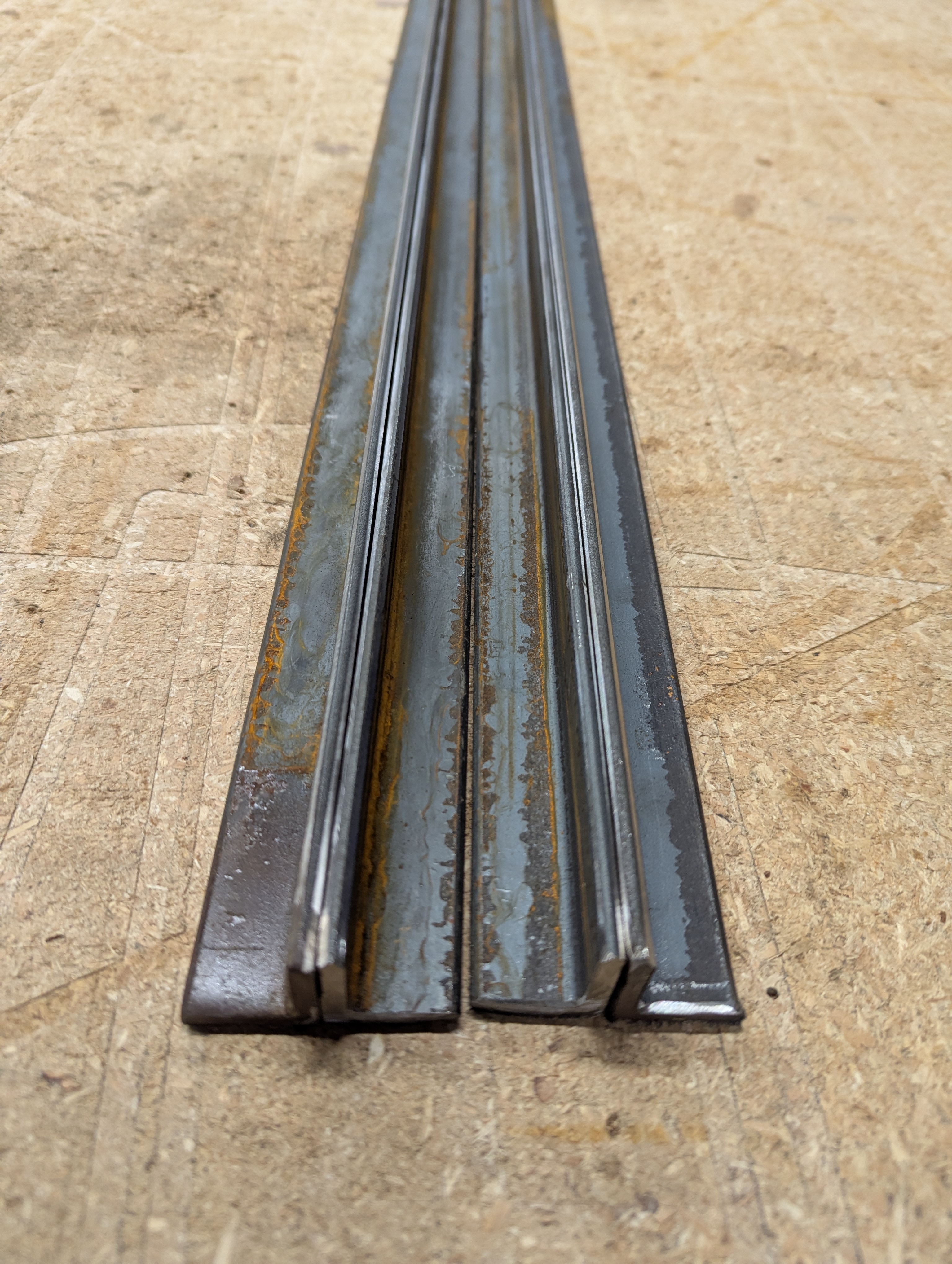
Here are four pieces ready to go. These started off as twenty foot long pieces all tied together every three or four feet. These look rusty and rough. This is typical.
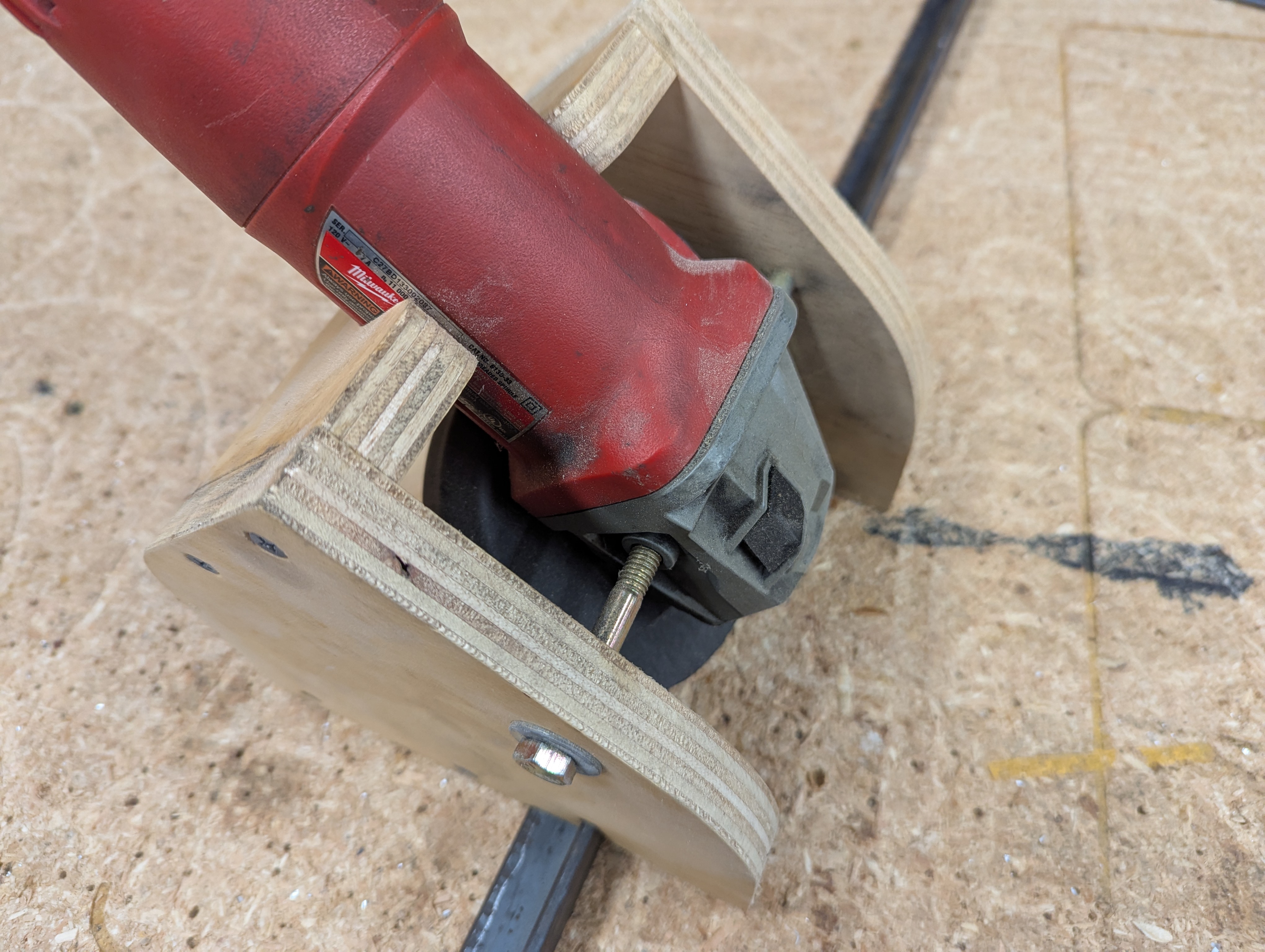
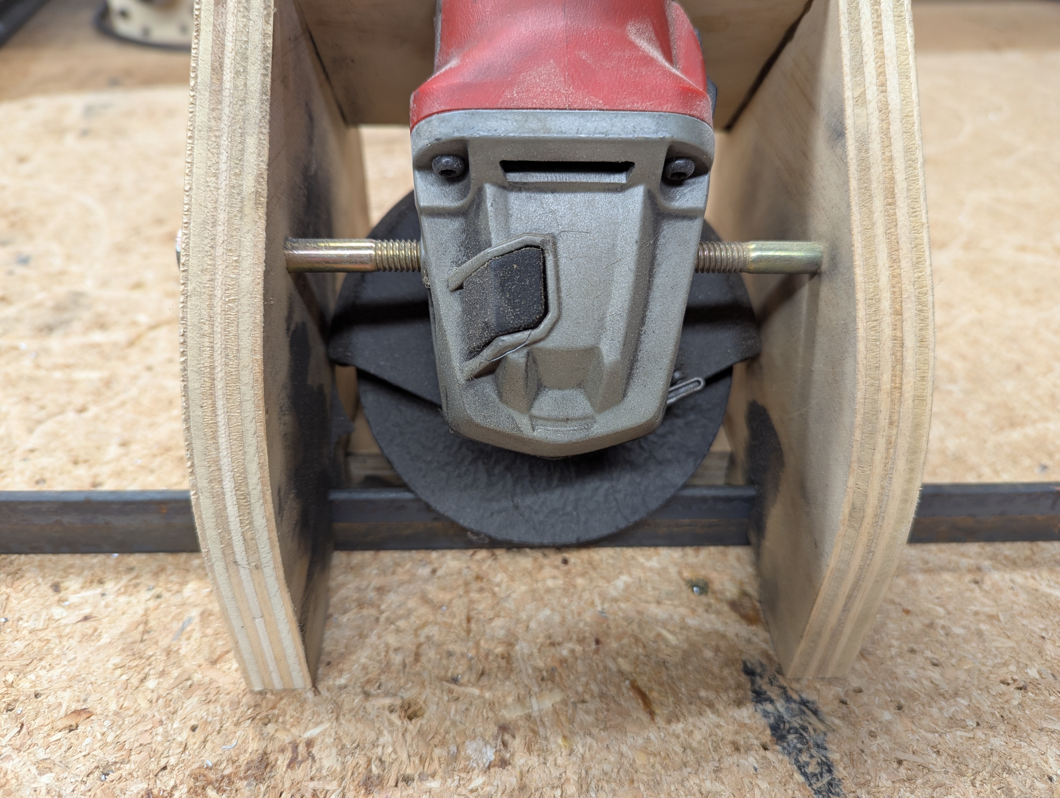
Grinding the Rails
V-groove bearings will ride along the top flange of the angle, and to make things smoother and a bit more accurate, the top is ground. On the last CNC table I built, I simply cleaned it up by hand with a file. This time I built a jig which holds an angle grinder.
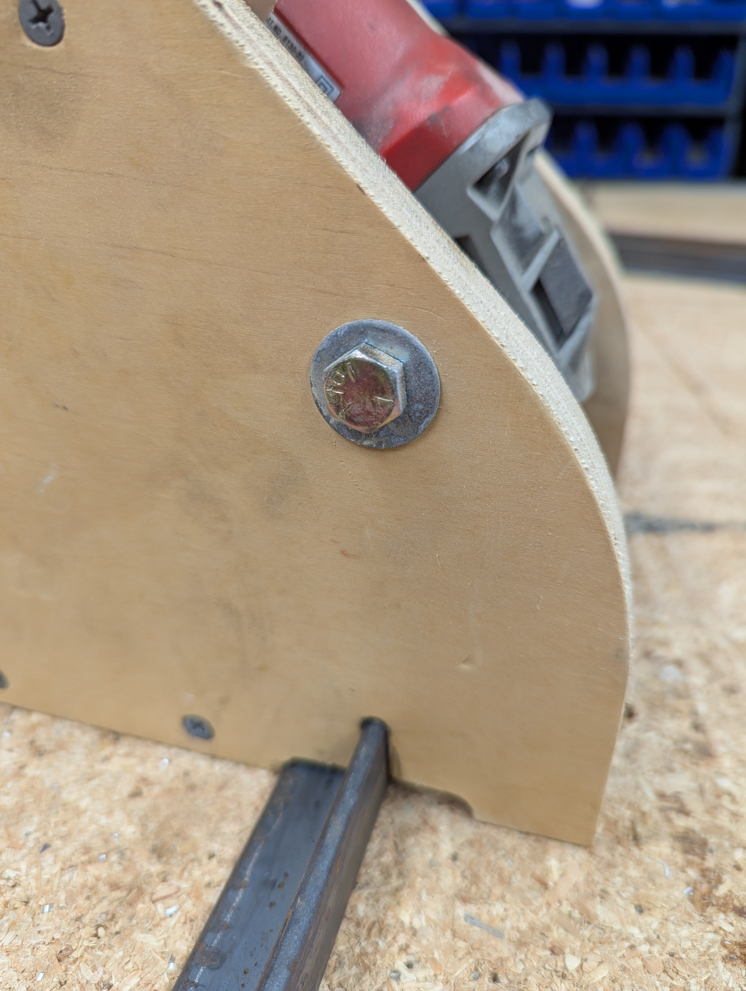
This jig holds the grinder at a 45 degree angle:
Not a whole lot needs to be ground off:
Try to make the ground flat about 1.5 mm wide. Actually, start with a 1.0 mm flat. Better yet, just knock off the edge. Then if you find a low spot grind everything down to that low spot. Worst case, grind to a flat 2.0 mm wide. Regardless, just make them all exactly the same.
You can eyeball this. It is easy to tell which areas need a little more... make the grinds even the whole length. No gouging. No high spots.
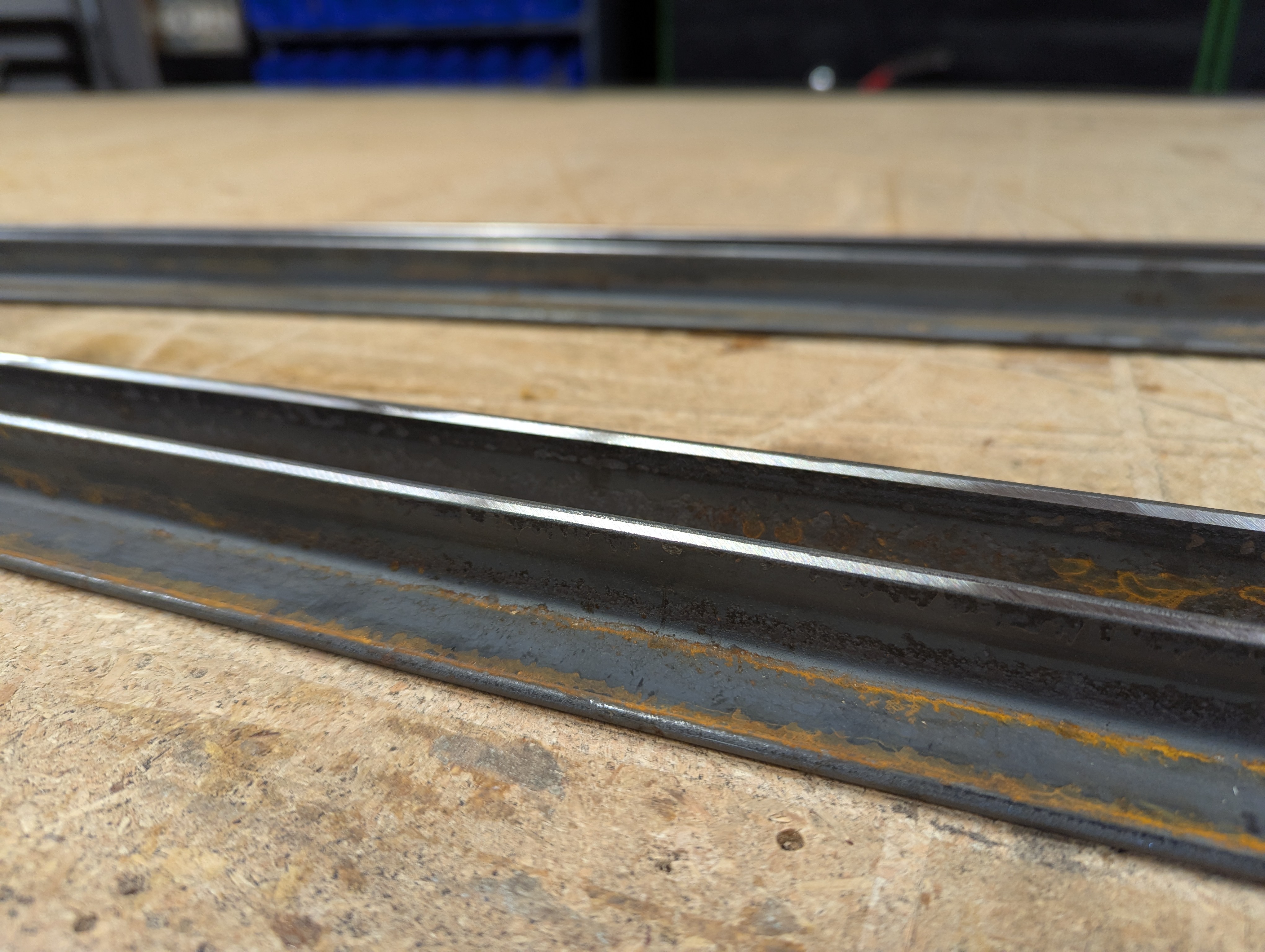
Not all pieces are extruded exactly the same. In this set, two were a little shorter (less than 1 x 1 inch) than the other two (you can not tell from the image, you have to measure). So I paired them so that the ones that will go on the top of the table are the same height, and the ones on the bottom are the same height.
Again, these look rusty and rough. This is typical:
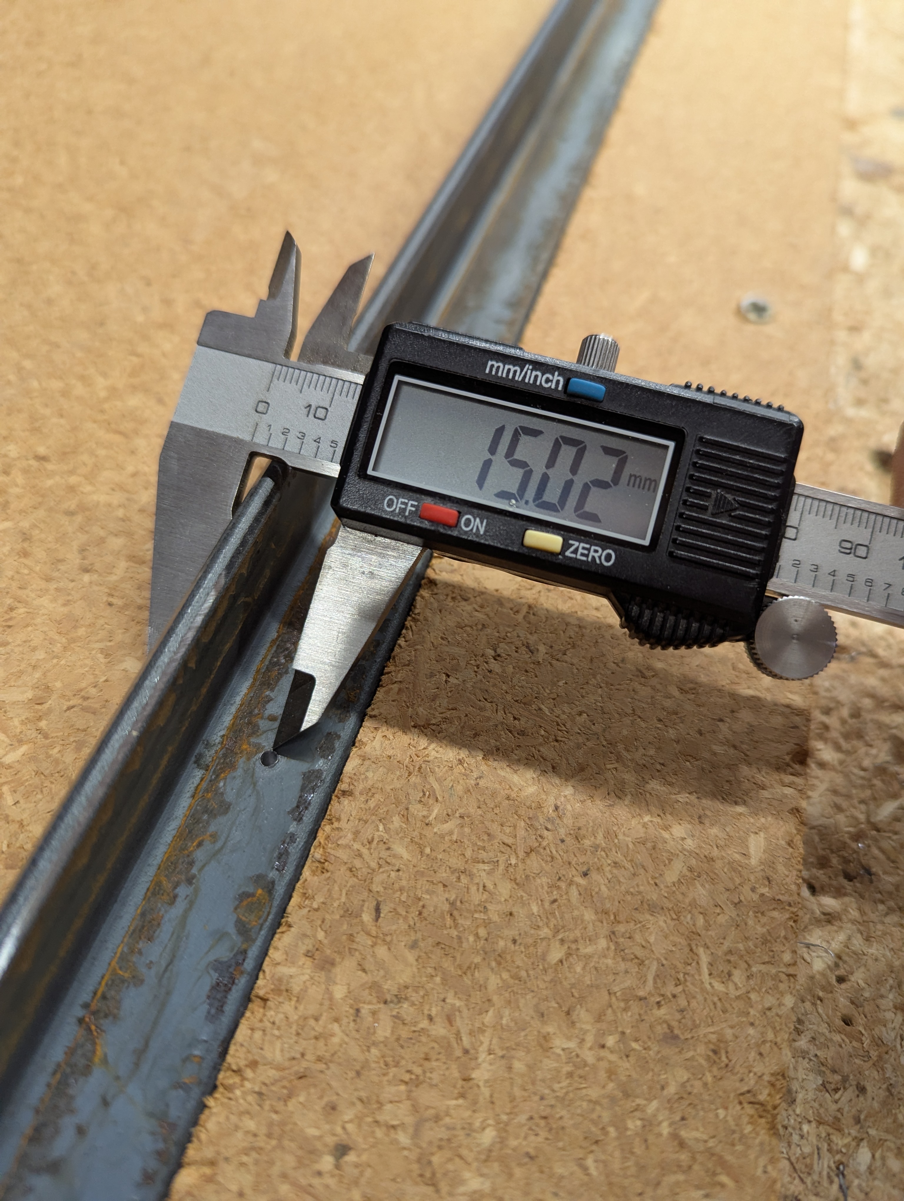
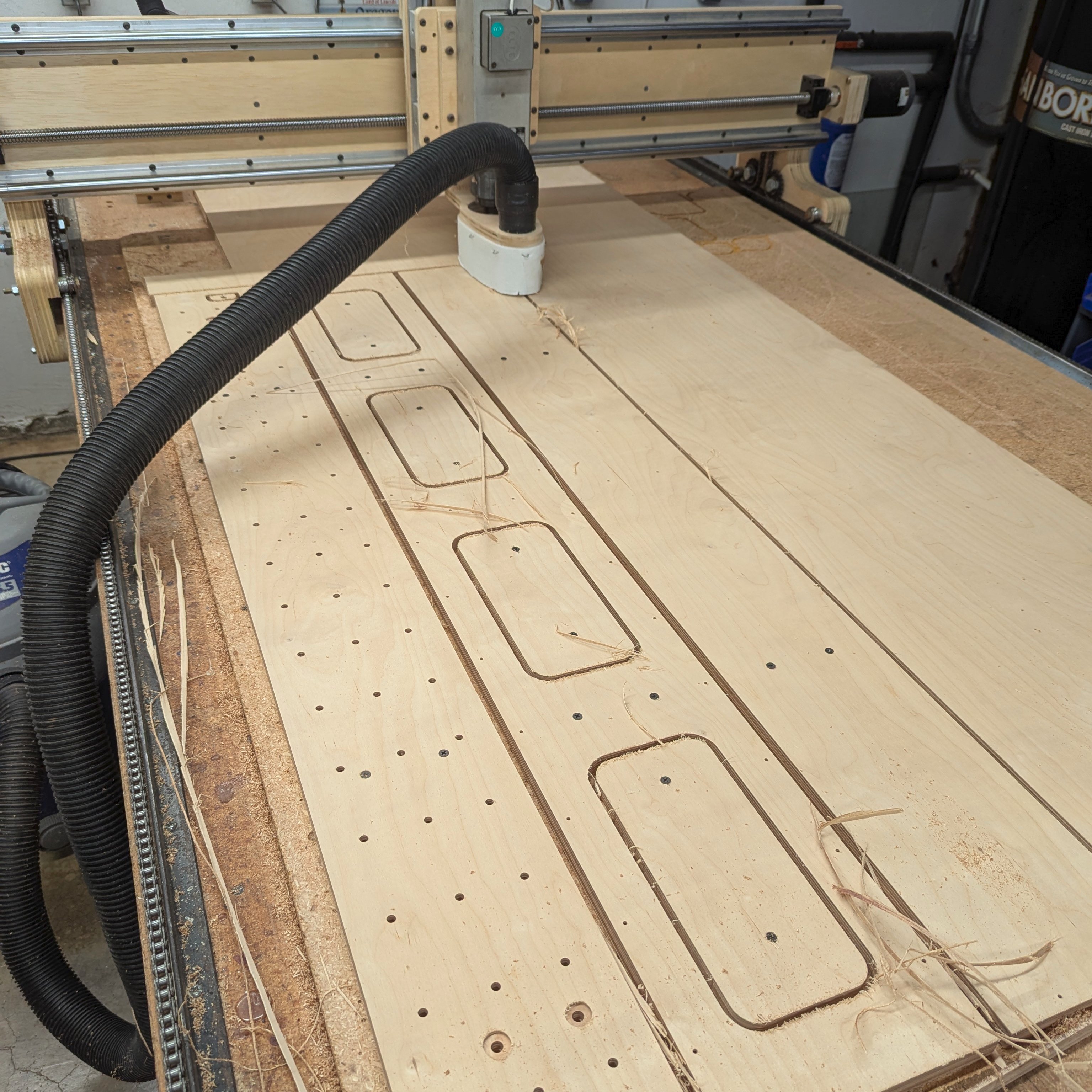
Drilling the Rails
The rails are connected to the table using M5x40 flat-head screws. The spacing needs to match that in the DXF file for the table. For this build the spacing was every 100 mm with the first 50 mm from the end. The position of the hole is 15 mm from the outside edge of the vertical side (roughly 10.4 mm from the tip of the horizontal side, depending on the accuracy of the steel extrusion).
You can measure and drill by hand, but with a CNC here are the steps:
-
Screw down a piece of scrap plywood/particle board as long as the rail.
-
Cut a precision slot the same width as the steel angle. At the same time, cut a precision edge defining the end of the rail.
-
Then the rails can be placed in the slot and the CNC drills the accurate holes. Easy.
Here is a time-lapse video of the slot being cut:
CNC Trick: On my first try my slot was too narrow. So I decreased the diameter of the tool in the CNC's tool table from 6.35 mm to 6.00 mm. I ran the program again and with that new setting the tool compensation offset was less and it cut closer to the defined edge.
For drilling I start with a small bit and work up to the desired hole diameter. My 3/32 inch bit gets a lot of use this way. My second pass on the CNC was with a 1/8 inch bit (yep, I only have a couple of collets for my spindle and the two small ones are 3/32 and 1/8).
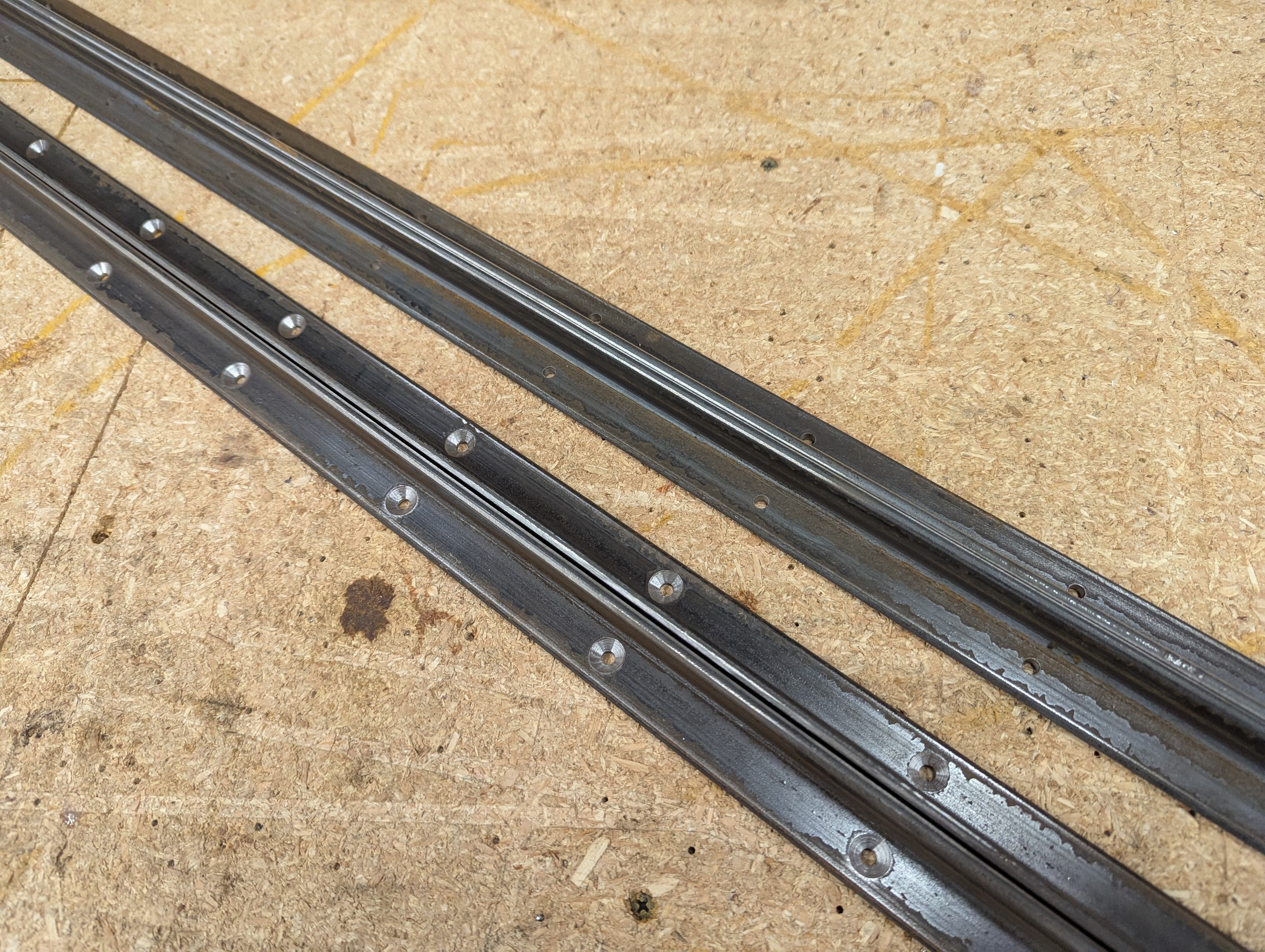
Here are a couple of the holes being drilled:
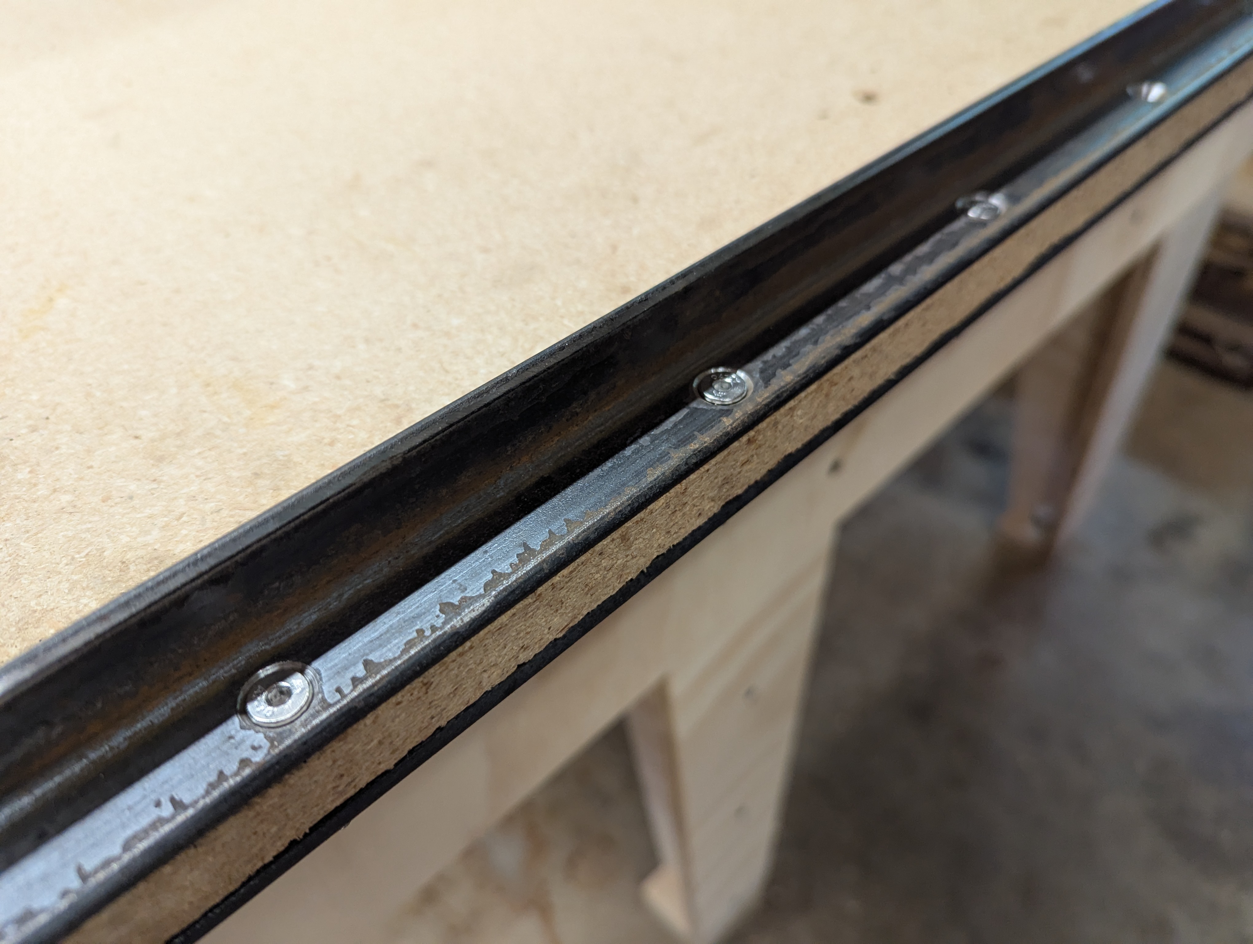
The holes are now spaced and positioned as noted above. The position of the hole is 15 mm from the outside edge of the vertical side:
I do not have a spindle collet for a 5 mm bit, so the final drilling and countersink were done on a drill press. I do not have an official Metric bit for a 5 mm clearance hole, so I used a #7 (5.11 mm, 0.201 inch). Countersink only the set of rails to be located on the top of the table. Here are the results:
Here is the DXF file I used to cut the slot and drill the holes:
WorktableCNC-RailDrillingJig.dxf
Installing the Rails
Since I used a top which was thicker than 18 mm, I milled the underside ends with a hand router to exactly 18 mm thick. This is where the rails will be located:
M5x40 flat-head screws were used. M5x35 would have been perfect, but that is an odd size. Either works fine:

Building the Gantry
Linear Rail Roller Adjustments
In an ideal world the top and bottom linear rails along the table would create a set of rolling surfaces which are exactly at the same distance from each other at all points along the table. In that case, both the top rollers and bottom rollers can perfectly engage the track. This never happens. So you have two options:
- You either build in some sort of flexibility.
- You design for the fact that the bottom rollers are not always touching.
Obviously you should try to make the track as perfect as possible. And if there is a skinny spot you should shim the bottom track, or regrind the track to make things even. I have owned several CNCs, and all of them with rollers on the bottom eventually get to the point where those rollers do not touch. You tighten things down, and the high spots on the track deform the system so rollers do not touch on the low spots. We are talking about tiny amounts here (like 0.2 mm / 0.010 inch). The only exception was a CNC with a thin plate as a gantry side and it was able to flex like a spring.
The design of this CNC expects that there will not be perfect engagement of the bottom rollers. The center of mass of the gantry was designed to be between the top rollers. If operated correctly, the gantry should never tip forward or back, and the nature of the V-groove bearings should allow the weight of the gantry to resist side-to-side forces. When not operated correctly, the bottom bearings keep the gantry in place.
Regardless, you should have some sort of method to adjust the rollers to get them as close as possible and initially touching with a little tension. With that, you have two options:
- Use eccentric bushings on the bottom bearings so their position can be adjusted.
- Customize the spacing of the bearings to match the rails as ground and installed on your table.
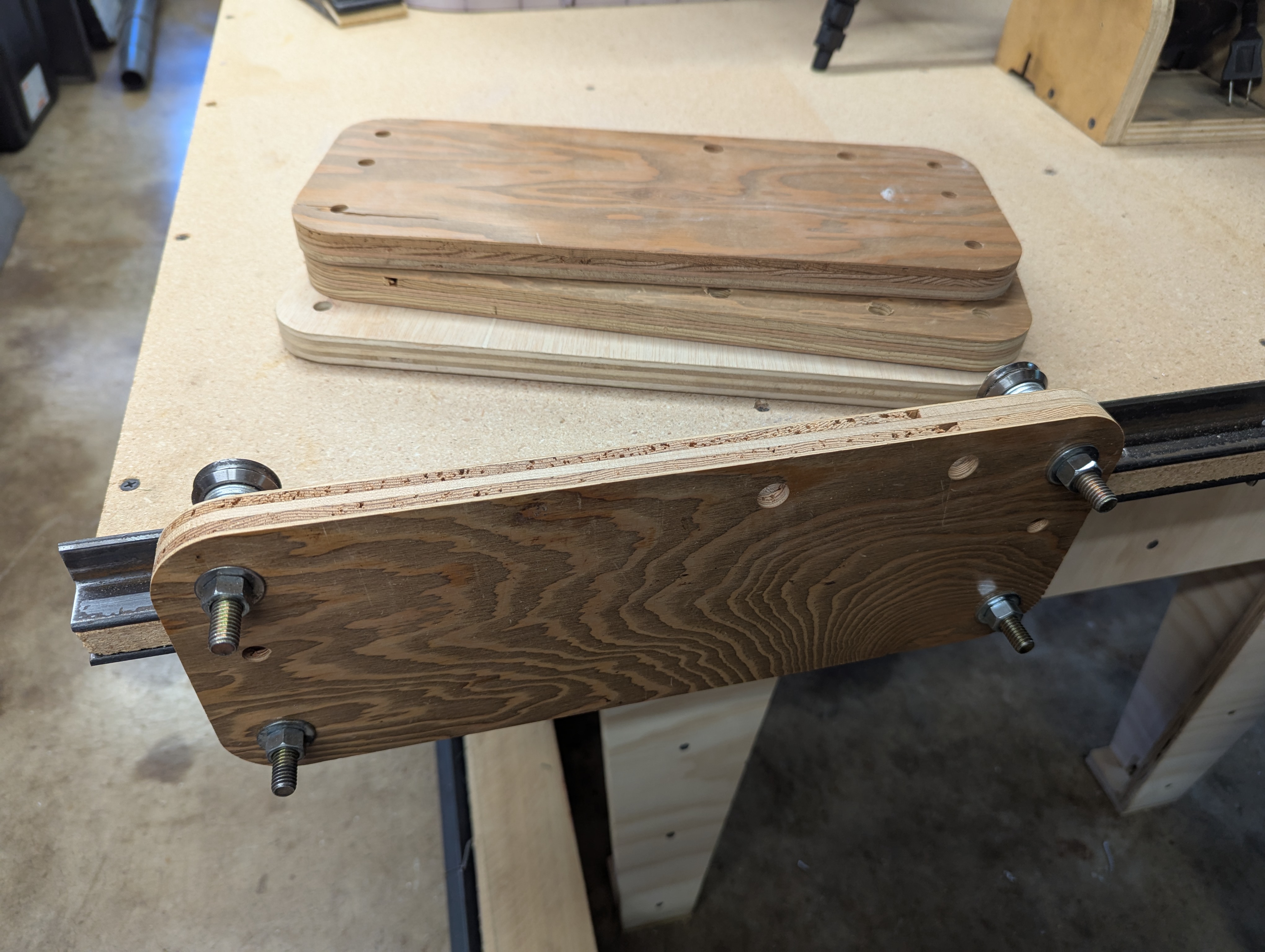
Eccentric bushings are expensive. I am a cheapskate. Here is how I did it:
I simply cut a template with the holes as designed on the gantry sides. When I found that the holes were too far apart, I cut another template with them a little closer. After four tries, I had the spacing perfect. I will use this spacing on the actual gantry sides.
Cutting the Gantry Parts
All of the plywood parts below are made from 18 mm thick, 13 layer, Baltic Birch cabinet grade plywood.
With the linear rail roller spacing sorted out as noted above, I updated the cutting file and cut out the side pieces. These will be laminated using three layers each side, so there are six side pieces.
I used a scrap piece of plywood and had exactly enough (sometimes you get lucky):

I also used a scrap piece to cut out the inner ribs (I got lucky twice):
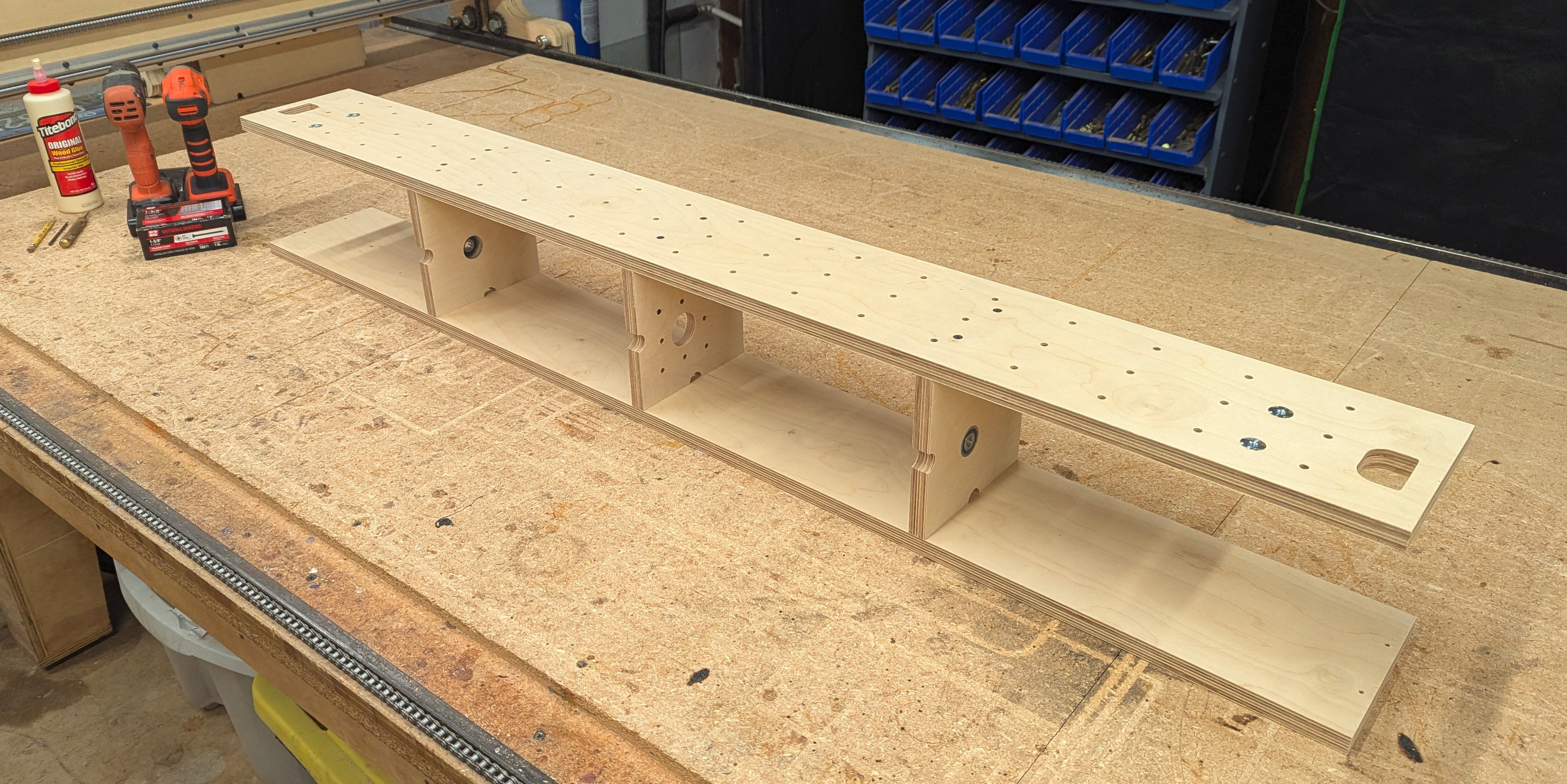
The gantry top, back, and bottom were cut:
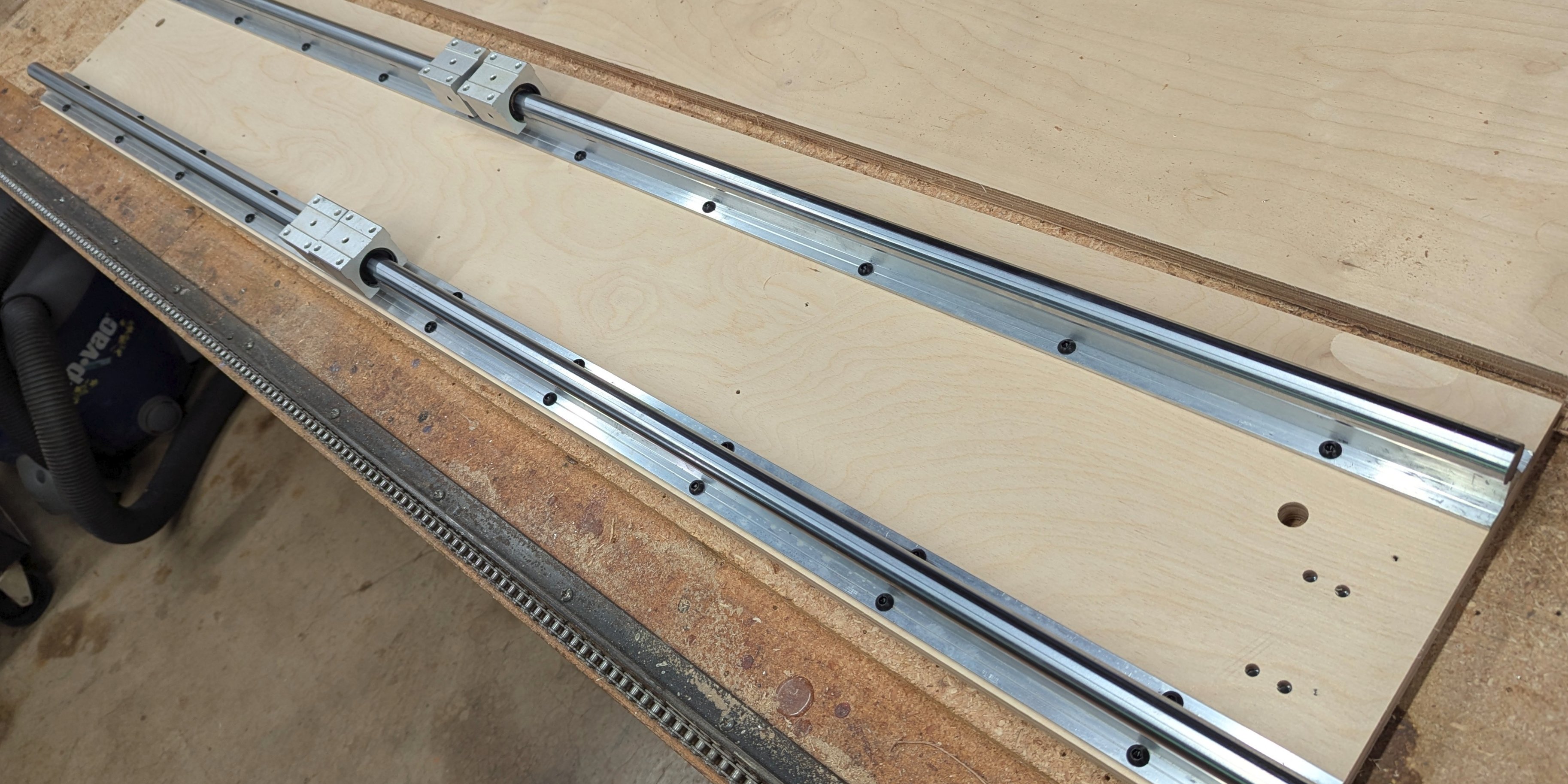
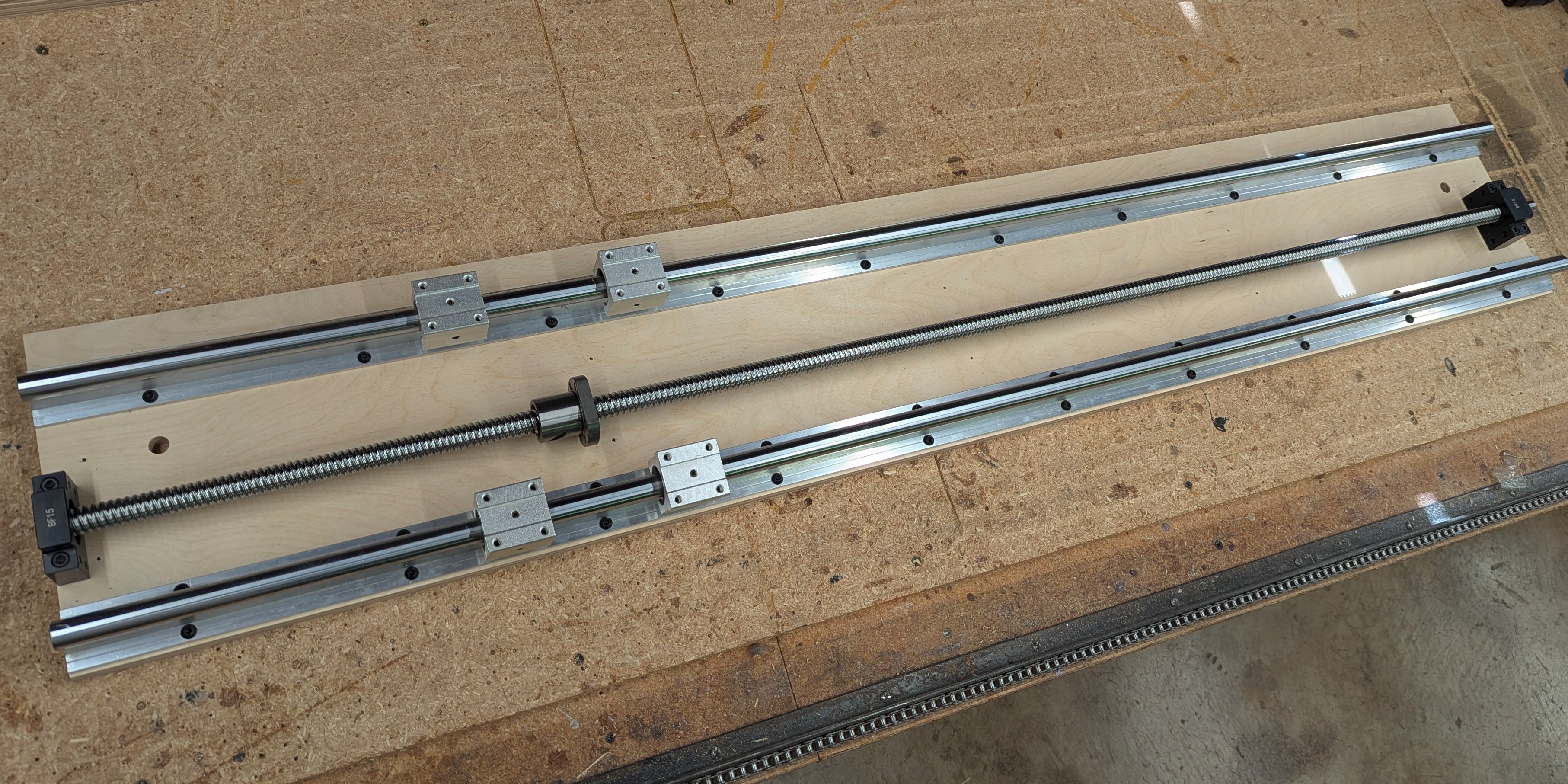
The Gantry Front
The hardware needed:
-
(2) Linear Slide Rails:
- SBR20 Rail (20 mm shaft x 1500 mm long)
- SBR20UU Blocks (2 per rail)
-
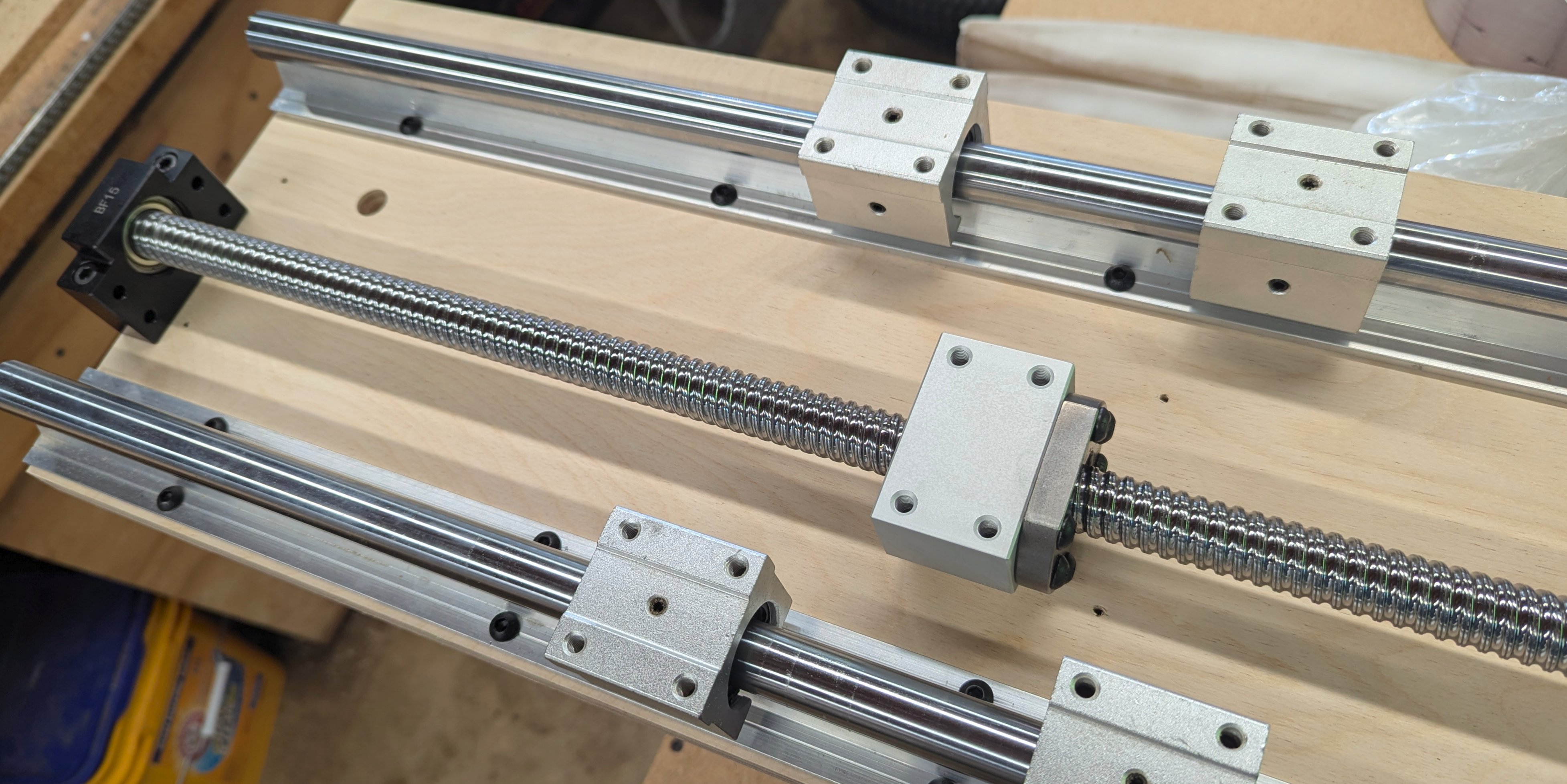
(1) Ball Screw:
- SFU2010 Screw (20 mm x 1500 mm long)
- SFU2010 Ball Screw Nut (10 mm pitch)
- DSG20H Nut Housing
- BK15 End Block
- BF15 End Block
- Coupler: sized to match screw to motor
-
(40) M6x20 button-head screws (rails).
-
(6) M6x50 cap-head screws (ball screw).
-
(46) M6 tee nuts. 18 mm diameter base, 10 mm tall.
-
(6) M6x20 button-head screws (ball screw nut to nut housing).
The gantry front is a bit more complicated. The drill holes to mount the rails have to match exactly the mounting holes in the rails, and the back side has to be recessed where the tee-nuts are inserted. So when cutting the front, you cut it face down.
A problem I have had in the past is that the linear rails were provided with inaccurate mounting hole spacing (offsets up to 1.5 mm). I solved this with a custom CAD file which matched the hole pattern for that rail set. I also had to ream out a couple of the holes to make it work.
When it is correct, the screws should just drop in! If you have to drive them in, it is not right! The result is that this interference will distort the gantry face.
Today was a good day: The rails were drilled correctly from the factory and everything lined up first try!

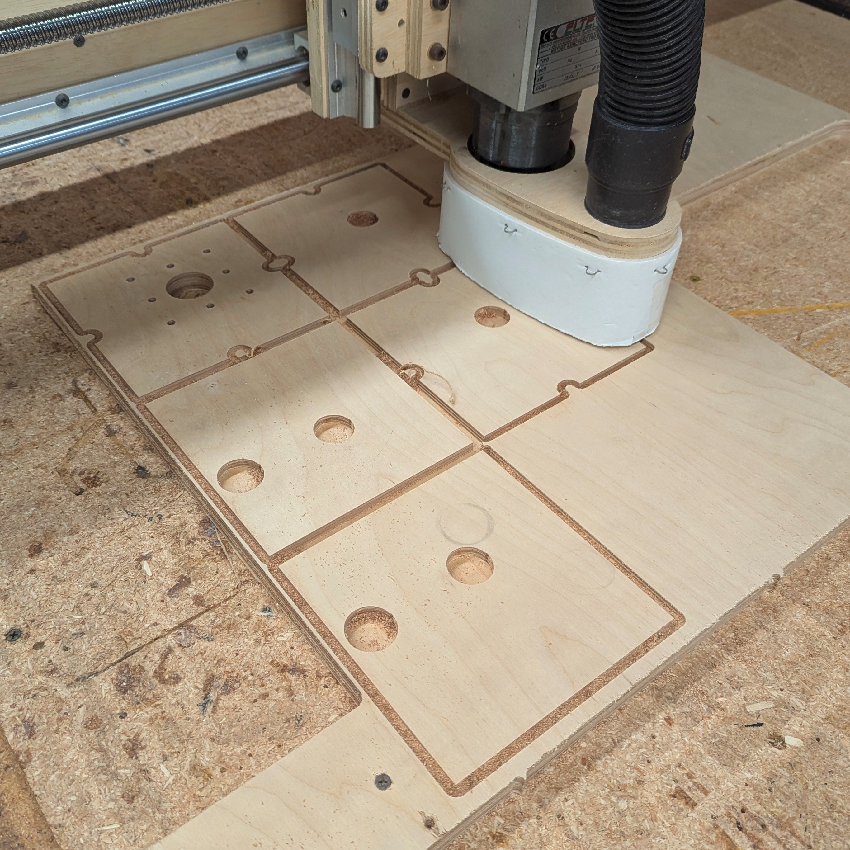
The tee nuts are hammered in before the gantry is assembled. In many places you can not insert them later. This is why we are using tee nuts; if we had access we would otherwise use regular nuts.
You can also see in the image below the recess cut for the tee nuts. There is a 6 mm through hole, an 8 mm hole to allow the nut body, and a 18 mm recess to allow the nut flange. The CNC did all of this for me, but I had to sand off the splinters.

A trick to keep from marring the plywood is place a piece of paper between the hammer and tee nut.

With all of the tee nuts in place, completely assemble the hardware to the gantry front. This ensures that everything is aligned accurately before you do a final glue-up of the gantry.
Two hardware assembly hints:
- The ball bearing in the end support block of the ball screw is pressed in at the factory at a random depth. You must adjust this so that with both blocks tightly installed on the screw the block mounting holes line up with those on the gantry front. Use a socket that touches the ball bearing outer race only, and tap with a hammer.

- That same end block is held in with a snap ring. Get actual snap ring pliers, you will need it enough to justify the purchase. And before you install that end block, this is a good time to install the ball screw nut housing to the nut (I always forget this step, but I have pliers so it is no big deal).
Gantry Ribs
The hardware needed:
- (4) 6200-2RS bearings (30 mm OD x 10 mm ID).
- (2) 6201-2RS bearings (32 mm OD x 12 mm ID).
There are five gantry ribs. The two end pieces are part of the side laminations. The center piece holds the stepper motor, and the neat cutout is sized for either a NEMA-23/24 or NEMA-34.
The holes for the bearings are routered with a climbing-cut, which typically leaves the hole slightly undersized. This way I can use a sander to open the hole to a light press-fit with the bearing.
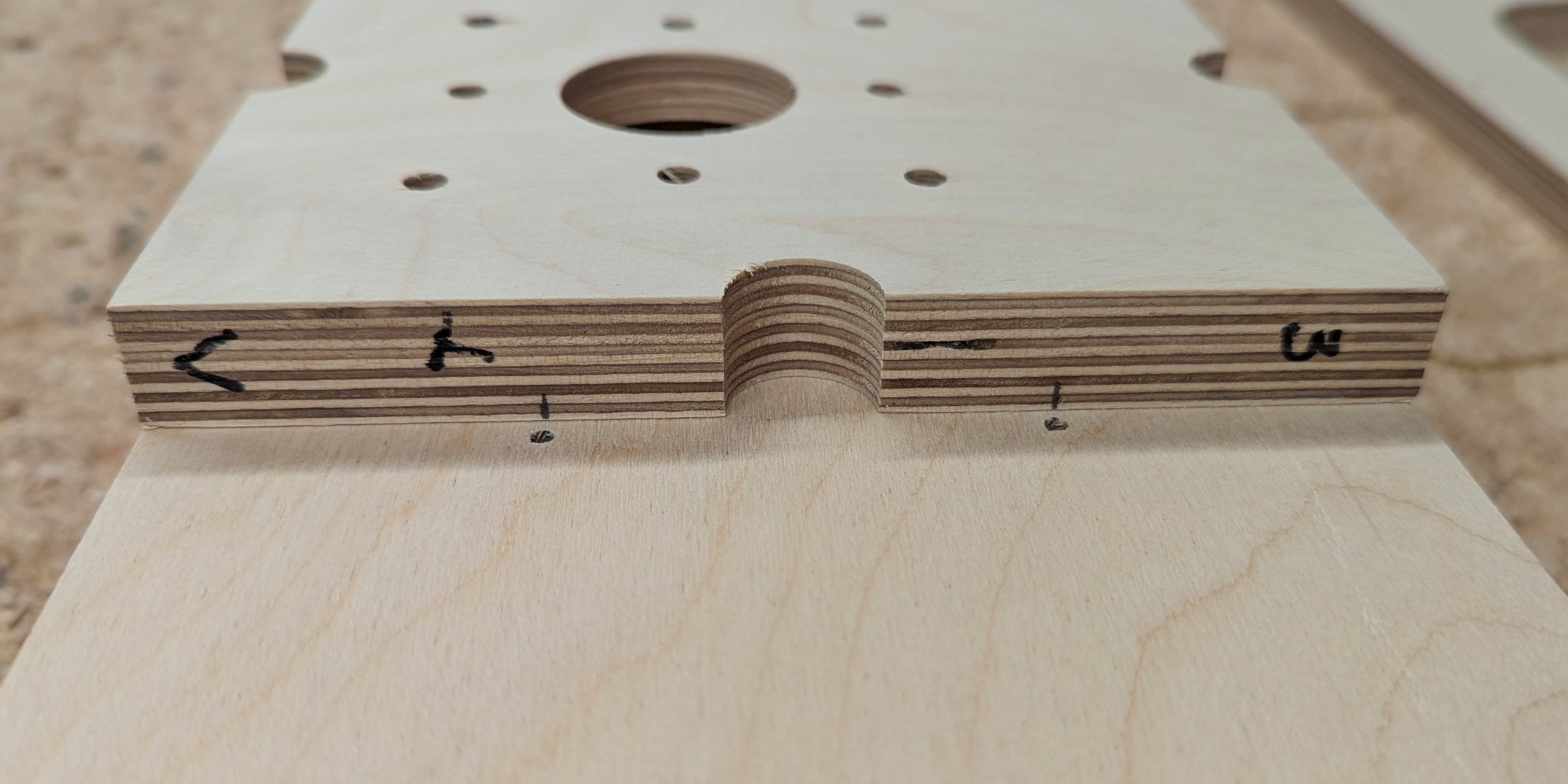
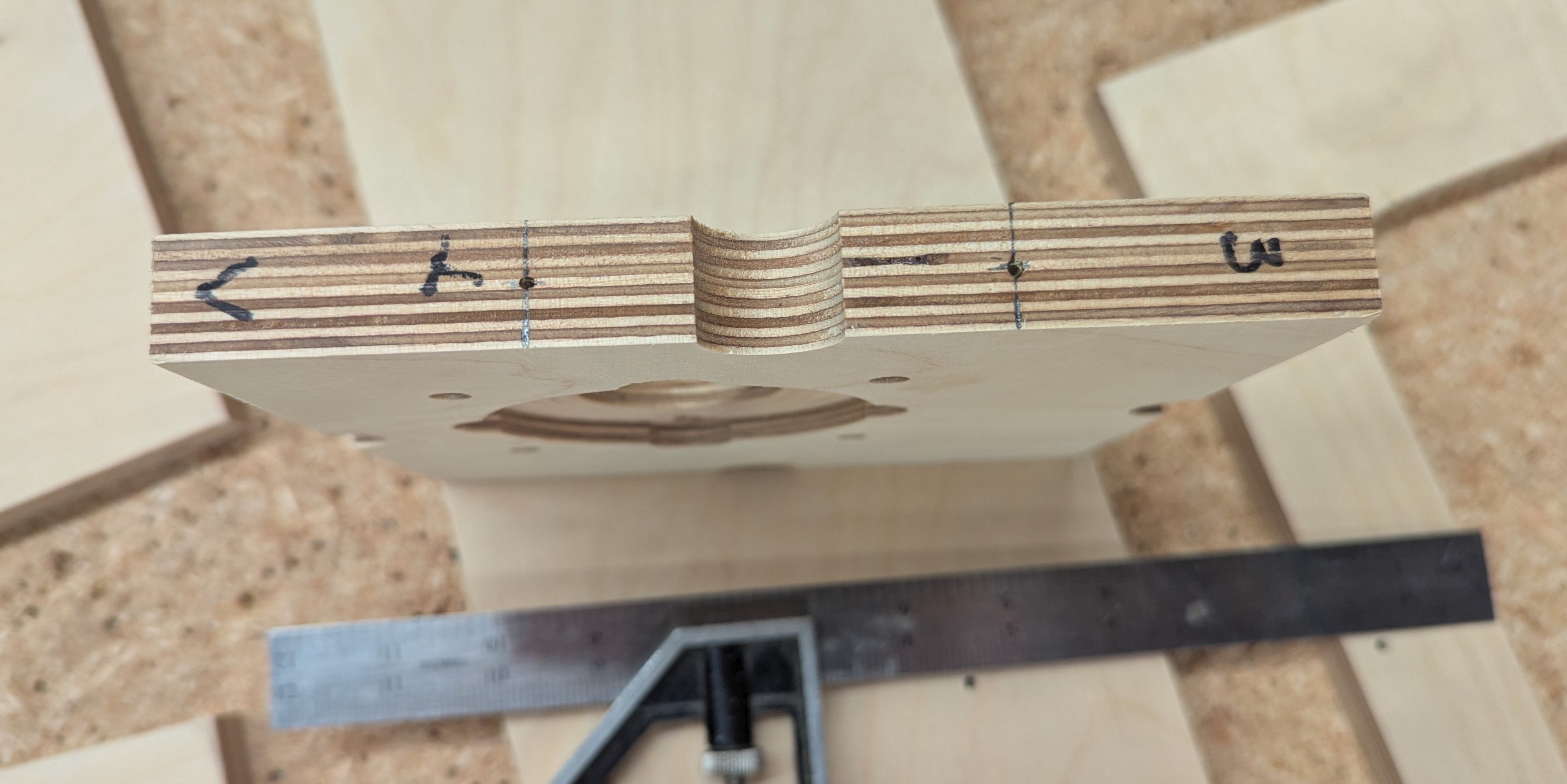
I also like to position the bearings so they are flush with one face, and the face is opposite of the opposite rib. Hard to explain, please just look at the images:
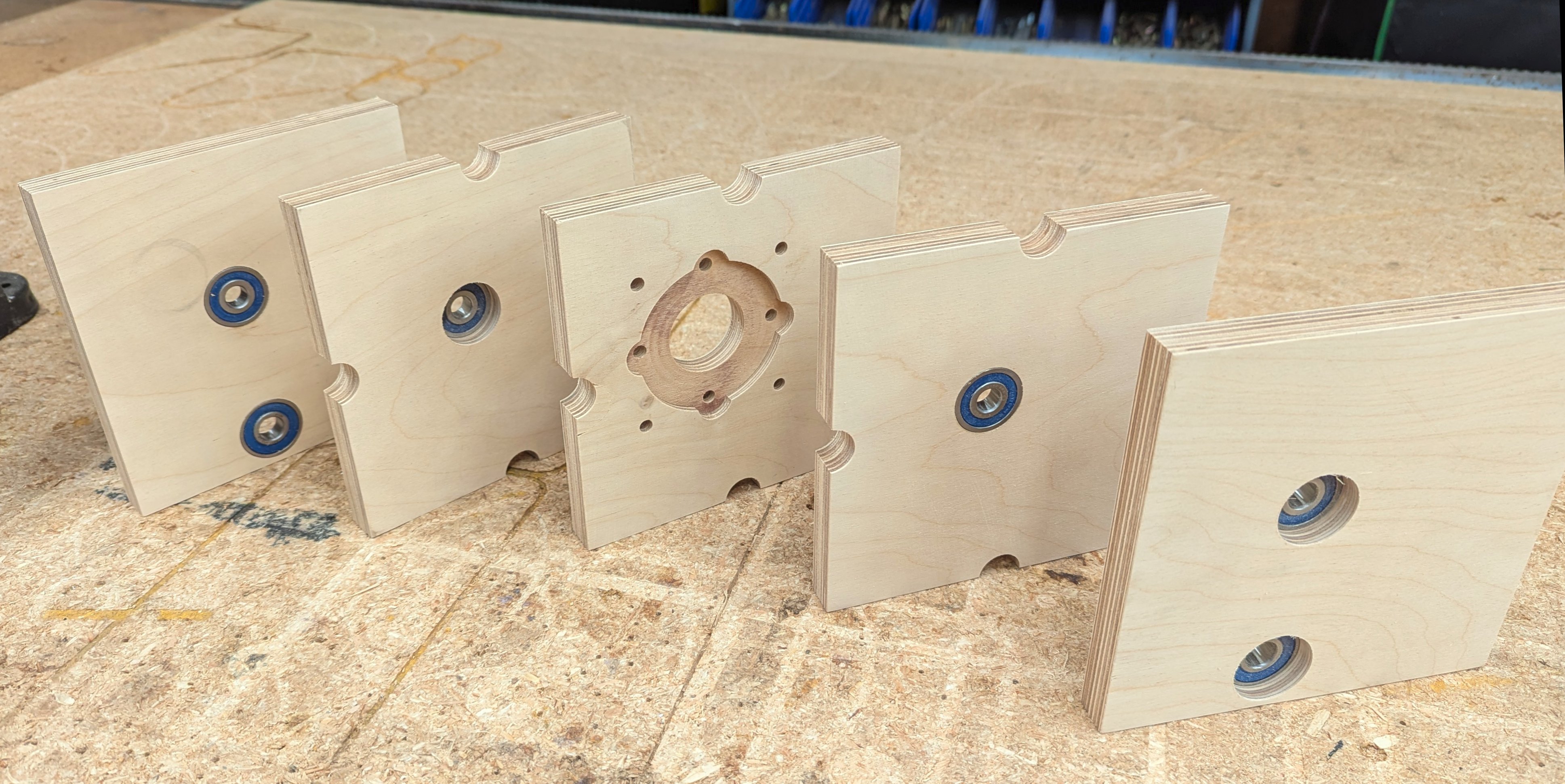
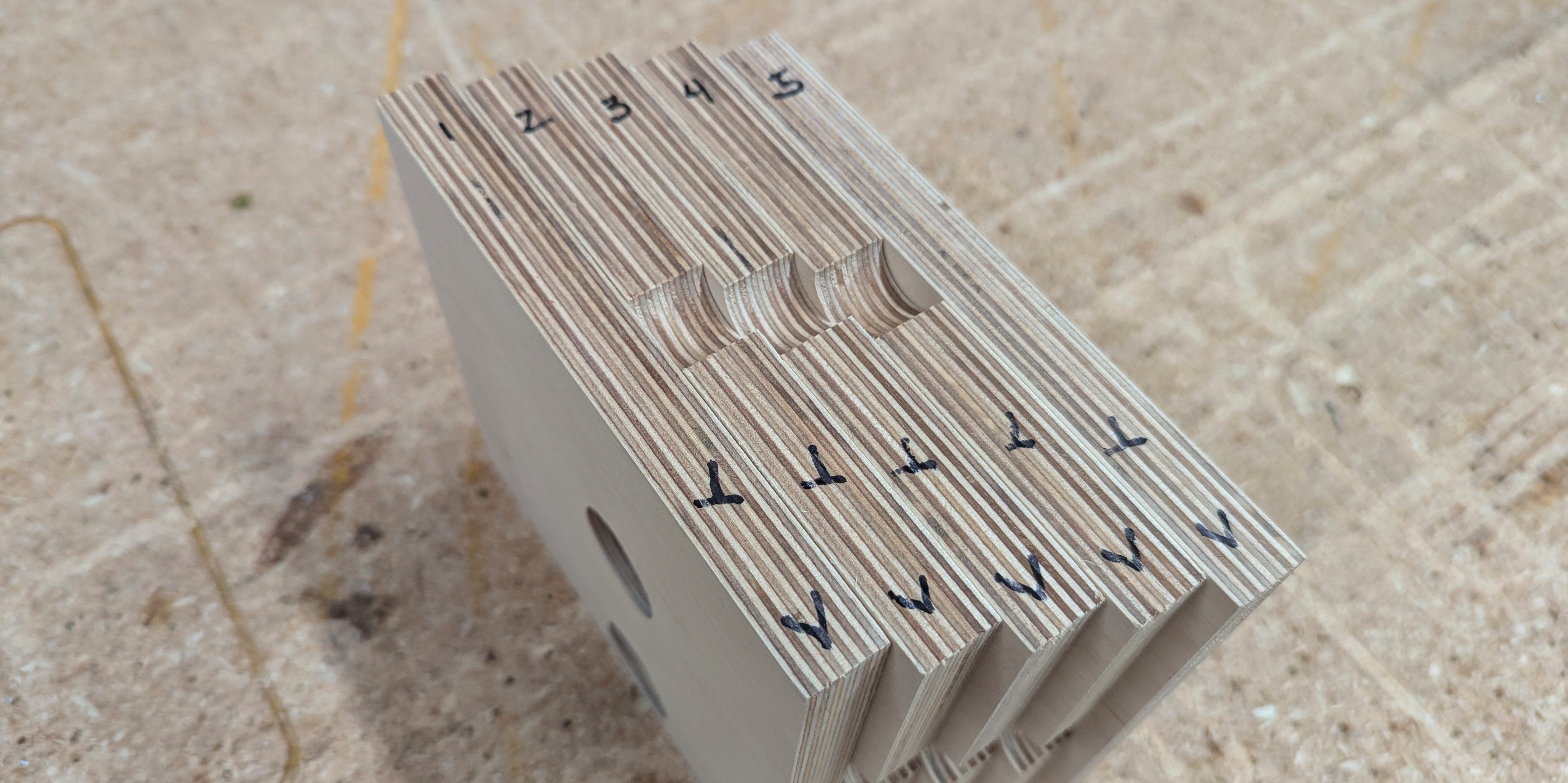
And it is really easy to assemble these in the wrong orientation. So mark a common edge and number the ribs:
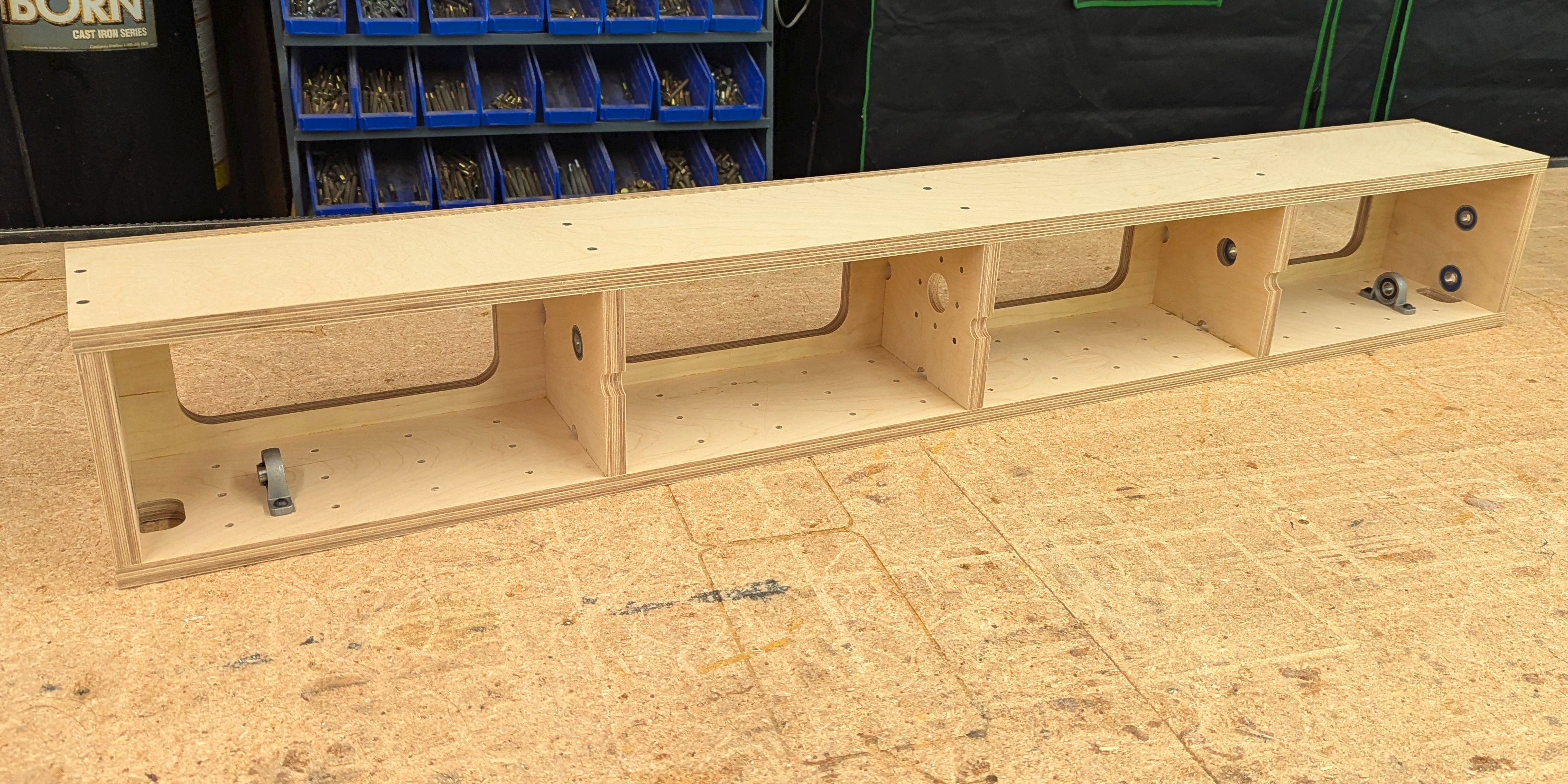
The Gantry Bottom
The hardware needed:
-
(2) Pillow Block Bearings:
- P001 or KP001
- 12 mm bore.
- 19 mm shaft center height.
- 56 mm screw spacing.
-
(4) M6x20 button-head screws.
-
(4) M6 tee nuts. 18 mm diameter base, 10 mm tall.
The bottom of the gantry has an opening on the ends for the drive chain to pass through. This and the bearing block line up with the bottom bearings on the ribs and the shaft opening on the end plates. Like the ribs, it is easy to orient this piece incorrectly so double check before assembly.
Install the nut plates and bearings at this point. It is easier to do this now since the nut plates need to be hammered in. This also checks to see if your bearings fit before you glue this part in permanently.
Assembling the Gantry
The gantry is simply held together with wood glue and drywall screws. You can get fancy an use stainless steel square drive screws, but I like the black look of a plain drywall screw. I typically like to use:
- Drywall screws: 1-5/8 inch fine-thread.
- Wood Glue: Titebond Original.
Basic wood glue is fine, it will not be located outdoors. But if you wanted to use Titebond II or III that is great, just more expensive. I would skip the weaker white glue.
Fine thread drywall screws (usually noted for metal studs) seem to screw in with a bit more control and do not seem to break as often. The 1-5/8 inch is about right, but I have also used longer.
Preparation for Screws
My CNC pre-drilled the holes to locate the screws. This was done with a 3 mm (1/8 inch) bit. This is not large enough for screw thread clearance. The screw will bite into this wood and it will have to rip it out before it tightens down what you are screwing into. So (depending on your screw) the location holes should be:
- Drilled out to 4 mm (5/32 inch).
- Countersunk to allow the head to crush just below the surface.
Pre-Drilling Edges
One trick I learned decades ago for centering a screw hole on a plywood edge:
- Lay the part on its side up against the part with the location holes.
- Position the part exactly and mark the hole locations.
- Using a square, scribe a line across the width of the plywood.
- Find the center lamination of the plywood.
- Center punch a start hole where the line meets that center.
- Pre-drill about a 1/4 inch down (just to get the screw started).
- When you glue and screw, it should all line up!


The Gantry Box Beam
The following pieces can easily be installed with an incorrect orientation. Double check!
Starting with the gantry top, the ribs are glued and screwed into place. As mentioned above, the location holes on the gantry top are drilled out and countersunk, and the edges of the ribs are partially pre-drilled for positioning.
With the ribs connected to the top, the gantry bottom is connected in the same fashion. The opening on the ends lines up with the bearings on the ribs, and the tee-nut clearance holes are on the bottom of the bottom.
Now the back can go on. The location holes are drilled out and countersunk, but it is not necessary at this point to do all of the above steps to locate the pre-drilled edge holes:
- Position the back exactly. It should lay in place with all edges lining up equally.
- Match drill down through the location holes on the back into the edges of the ribs, top, and bottom.
- Drill out and countersink the back.
- Remove, sand all of the drill burrs smooth.
- Glue and screw.
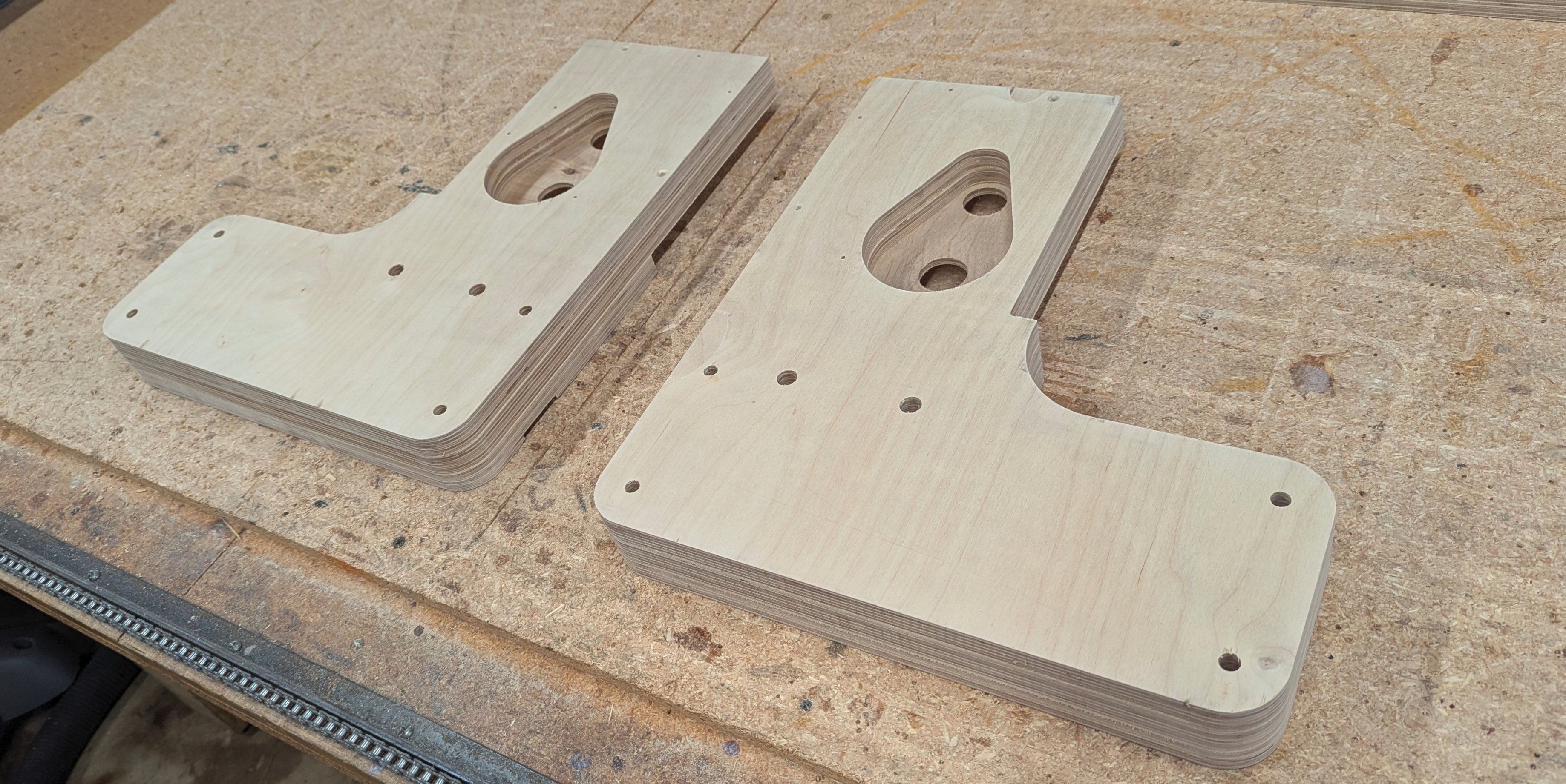
The Gantry Side Plates
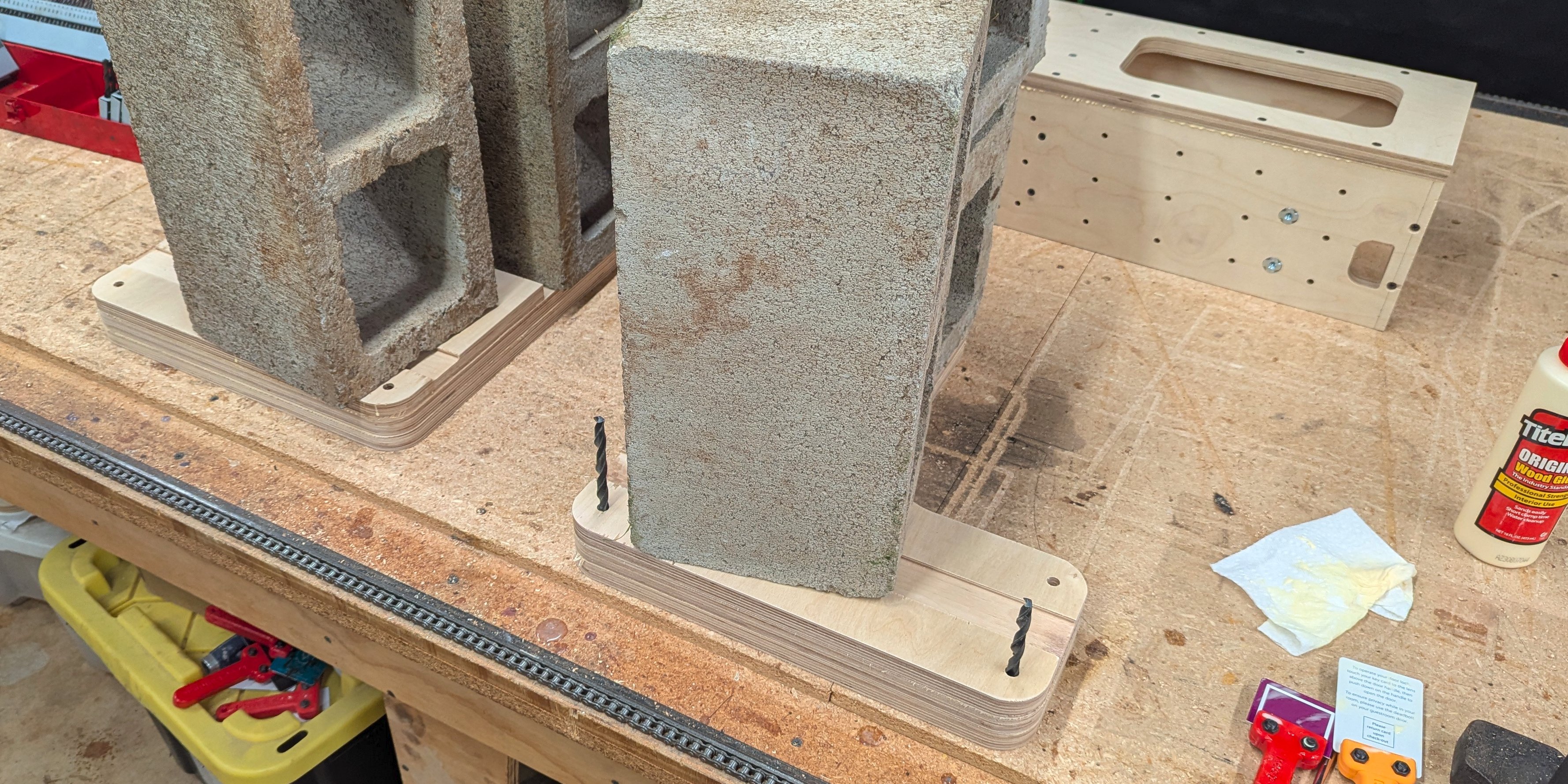
The three layers of side plates are laminated using wood glue. Spread the glue in an even thin layer:

Either clamp them together or weigh them down until the glue is set. Make sure the laminations are aligned perfectly!
At this point you need to check to see if the 3/8 inch and 1/2 inch bolts fit. Ream those holes as necessary; use a drill press. And, sand the edges now. All of this is easier with the side plates not yet connected.