CycleKart Build
The following page details the construction of two CycleKarts. What is a CycleKart? The details can be found here:
The Original CycleKart Webpage
CycleKart Specifications
Our buddy Vince started building one, and not to be left out Ernie and I decided to each build one too!
This project is still underway, so this webpage will seem a bit unfinished and disorganized. I add to it as the build progresses, so please keep checking in!
Picking an Inspiration Car
Each CycleKart is typically based on an existing car of a specific time period. This is called the Inspiration Car. It does not have to be an exact scaled-down version of the car, it just needs to kind of look like it. Picking an inspiration car is the first step of the build.
My inspiration car is a 1924 Fronty Ford Indy race car.
Ernie is building a ???.
Vince is building a Bugatti Type 35.
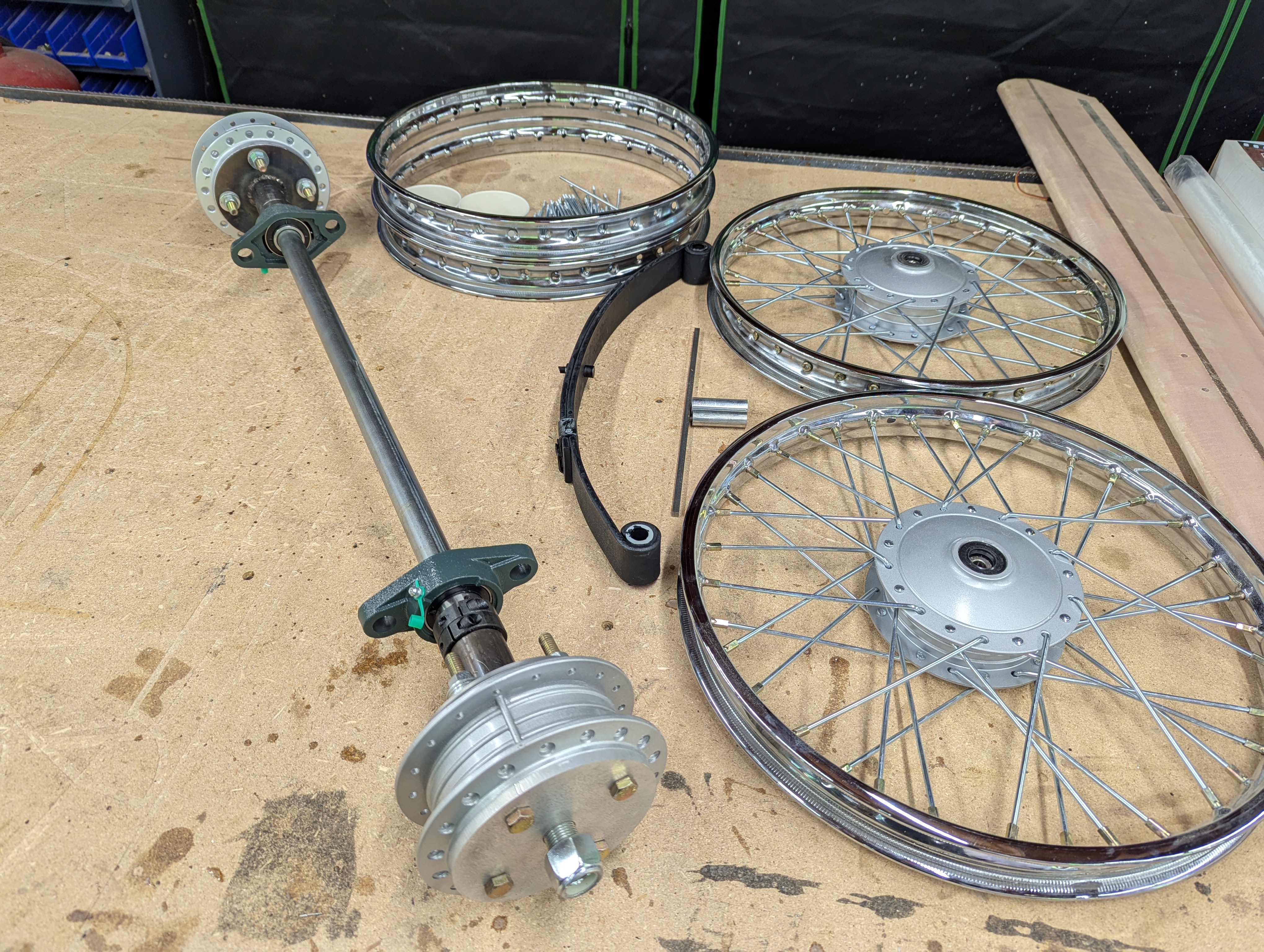
Wheels and Hubs
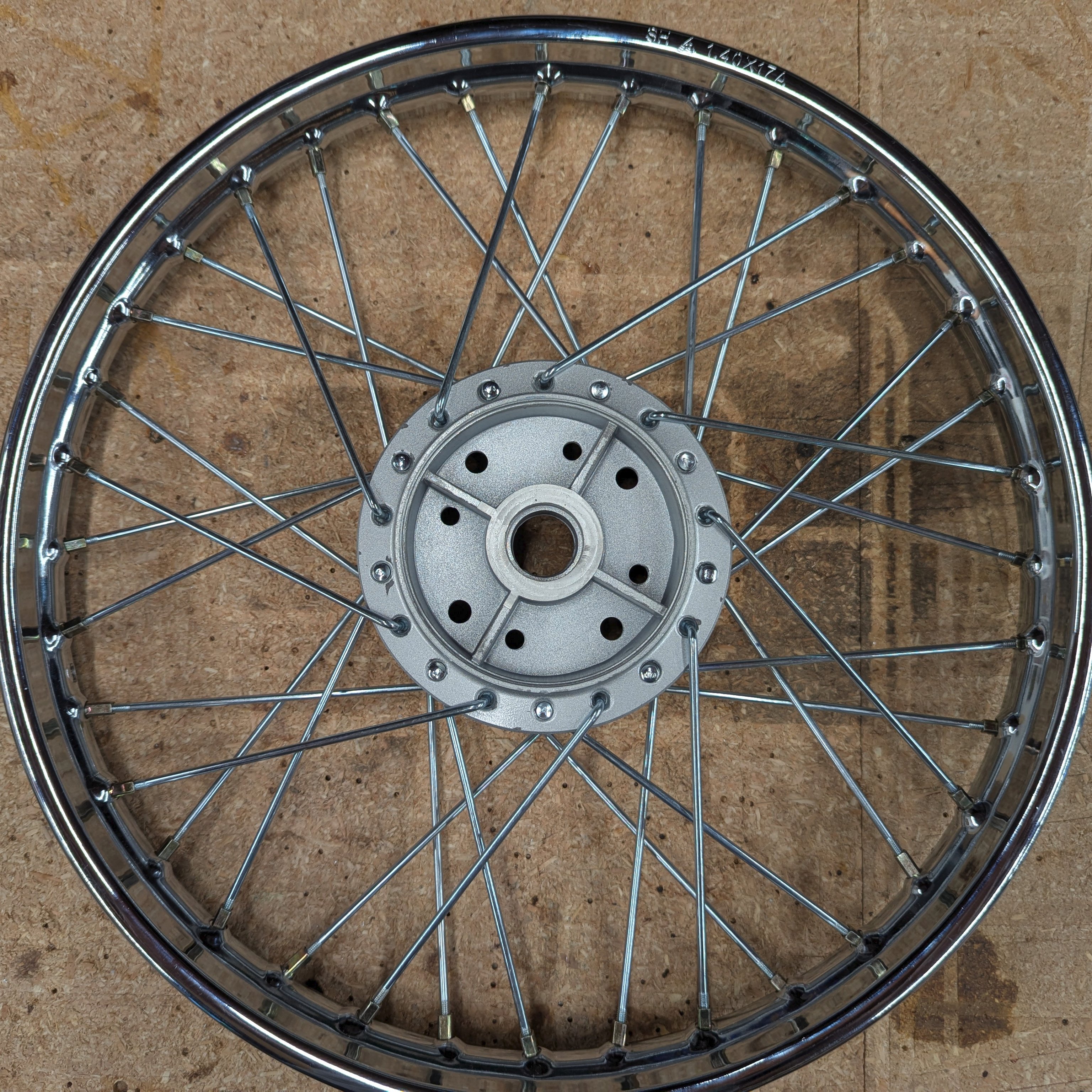
The wheels are from a Honda Trail 90. Apparently, replacement wheels are still being manufactured in Taiwan (these are the good ones), and reproduction wheels in China (these are generally problematic).
Purchased from eBay, I got a set from China. Maybe they all come from the same place and the cheap ones (the ones that I got) are the mistakes they made at the factory. None of my wheels were the same, and anything machined was inconsistent, not aligned, etc. I paid about $160 for the set delivered.
Ernie got a set from Taiwan. The castings were correct and every machined and drilled feature was accurate. Ernie paid just under $500 for the set delivered.
Front Wheels
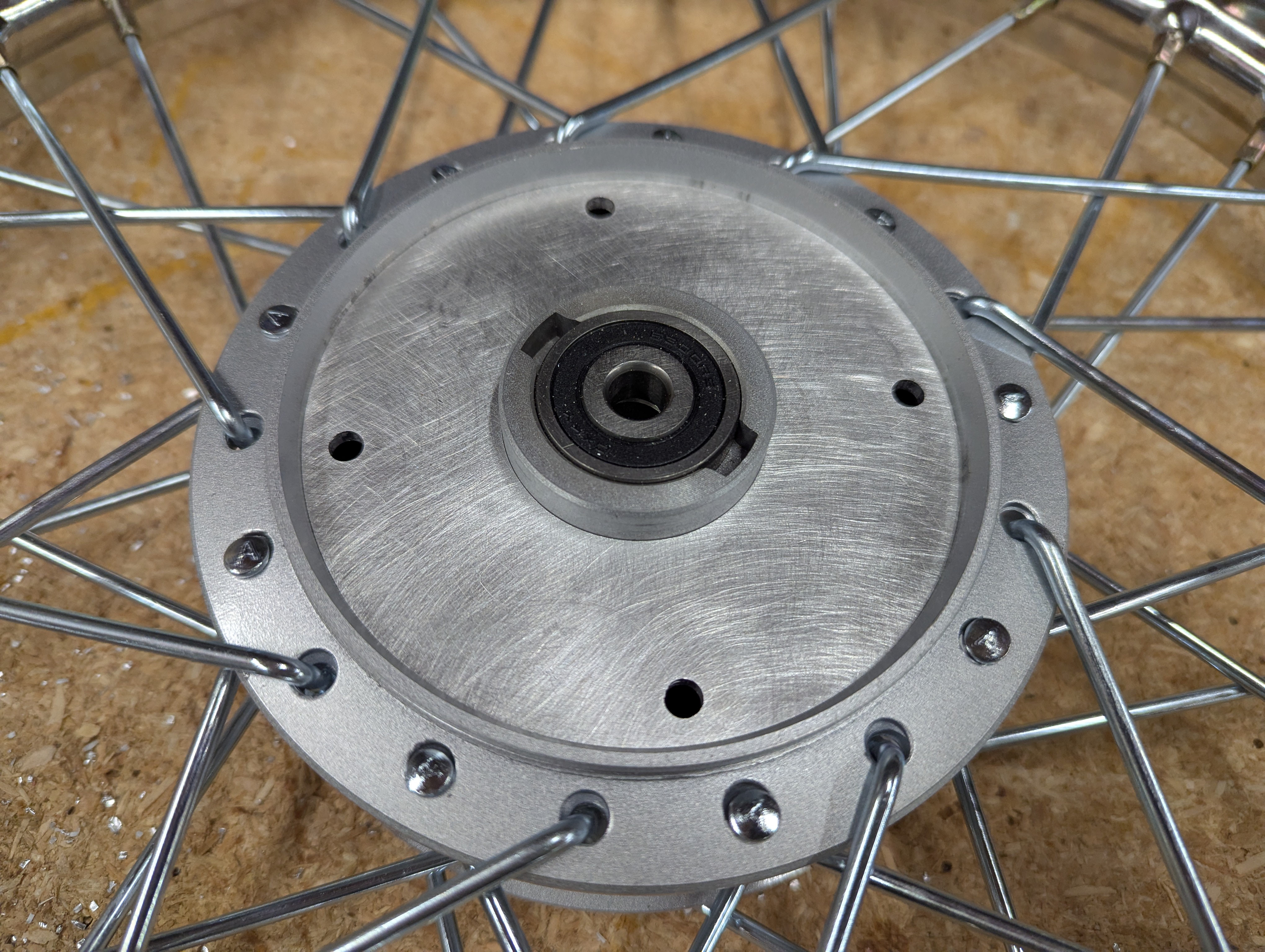
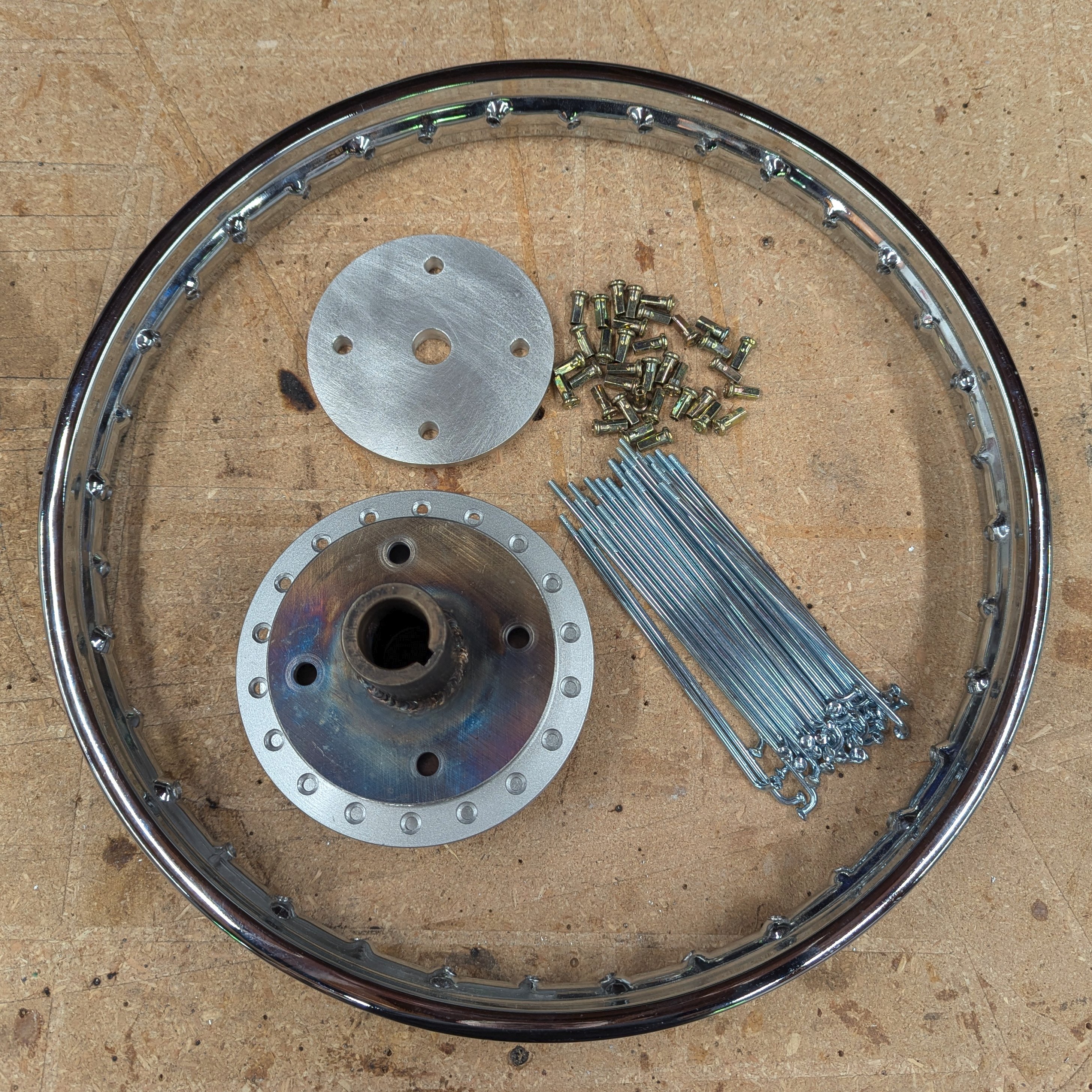
Both the front and back wheels are setup for drum brakes, and this results in a wheel design which could use a bit of extra support. To help strengthen the wheel-hub on the fronts, an aluminum plate was machined and pressed in.
In the images below, you can see the open area of the wheel-hub (the center is cantilevered off of a thin casting on one side), a prototype cut from thin aluminum, and the final support plate. The plate thickness is 2 mm (0.080 inch) and the four holes are just to be able to pull it out if needed. Although it is pressed in, on final assembly I may to use "green" Locktite (wicking grade) to really get it held in.

Front Wheel Bearings
The front wheels in the CycleKart spin on ball bearings, but the bearings on the motorcycle have a 10 mm inside diameter (ID). This is fine on a motorcycle since the 10 mm wheel shaft/bolt is supported on each end. On a CycleKart the shaft is cantilevered (supported on only one end) and 10 mm is not large enough; it would bend or break off. So it is common practice to use a 5/8 or 3/4 inch axle shaft.
Here is the engineering trade-off: You are stuck using a 35 mm bearing outside diameter (OD) because of the wheel hub. So by increasing the axle shaft you end up with a weaker bearing. To better explain:
-
A 6300 series Medium-Duty bearing is a deep groove ball bearing. There is enough race material to surround the balls in a deep groove and the result is the axial load (side force) rating is about equal to the rated bearing load.
-
A 6200 series Light-Duty bearing has a little less race material. The ID hole can be a little larger. The downside is that axial load is a little less.
-
A 6000 series Extra-Light-Duty bearing has even less race material. This allows the biggest ID for a given OD, but the bearing load is less and the axial load is notably less.
For a 35 mm OD, the standard bearing choices are:
- 6300 (35 mm OD, 10 mm ID)
- 6202 (35 mm OD, 15 mm ID)
- 6003 (35 mm OD, 17 mm ID)
To use a 5/8 inch shaft you need a 6202-5/8 (the inch ID makes it a less common bearing). For a 3/4 inch shaft you need a really odd 6000 series bearing. So the common CycleKart practice of using the bigger 3/4 inch shaft forces one to use a really weak and expensive bearing.
Please forgive me, but I will be stick with a standard 6202 spinning on a 15 mm shaft!
Rear Wheels
The rear wheels are fixed to the 1 inch diameter rear shaft. Unlike with the motorcycle, the rear wheels do not freely turn on bearings and so the whole bearing center is unused. So this bearing center can be removed.
My plan is to support the wheel on the shaft using plates on both the inside and outside of the wheel-hub.
Most CycleKart setups do not include this extra support. Most rear wheels are supported only by either four mounting bolts connected to the thin cast aluminum web or by a matched diameter plate fitted to the inside of the wheel-hub only. My inside steel plate is match machined, but my aluminum outside plate is too, and it is machined to fit on the 3/4 inch step on the axle. In other words, both my inside and outside plates are supported by the shaft and supporting the wheel-hub. This distributes the loads to both sides of this cast aluminum wheel-hub.
I learned a lesson: If I ever do this again I will remove the spokes and rim first! You see why below.
To make it easier to understand what I am doing in the images, here is the list of steps:
- Mill out and remove the bearing center.
- Cut an aluminum plate to support the outside of the wheel-hub.
- Finish this plate on the lathe to an exact fit.
- Cut a steel plate to support the inside of the wheel-hub.
- Weld the steel plate to a steel weld-on hub.
- Finish this plate on the lathe to an exact fit.
- Print a 3D jig to locate the bolt holes.
- Drill out bolt holes on the steel plate.
- Match drill the bolt holes through the wheel-hub.
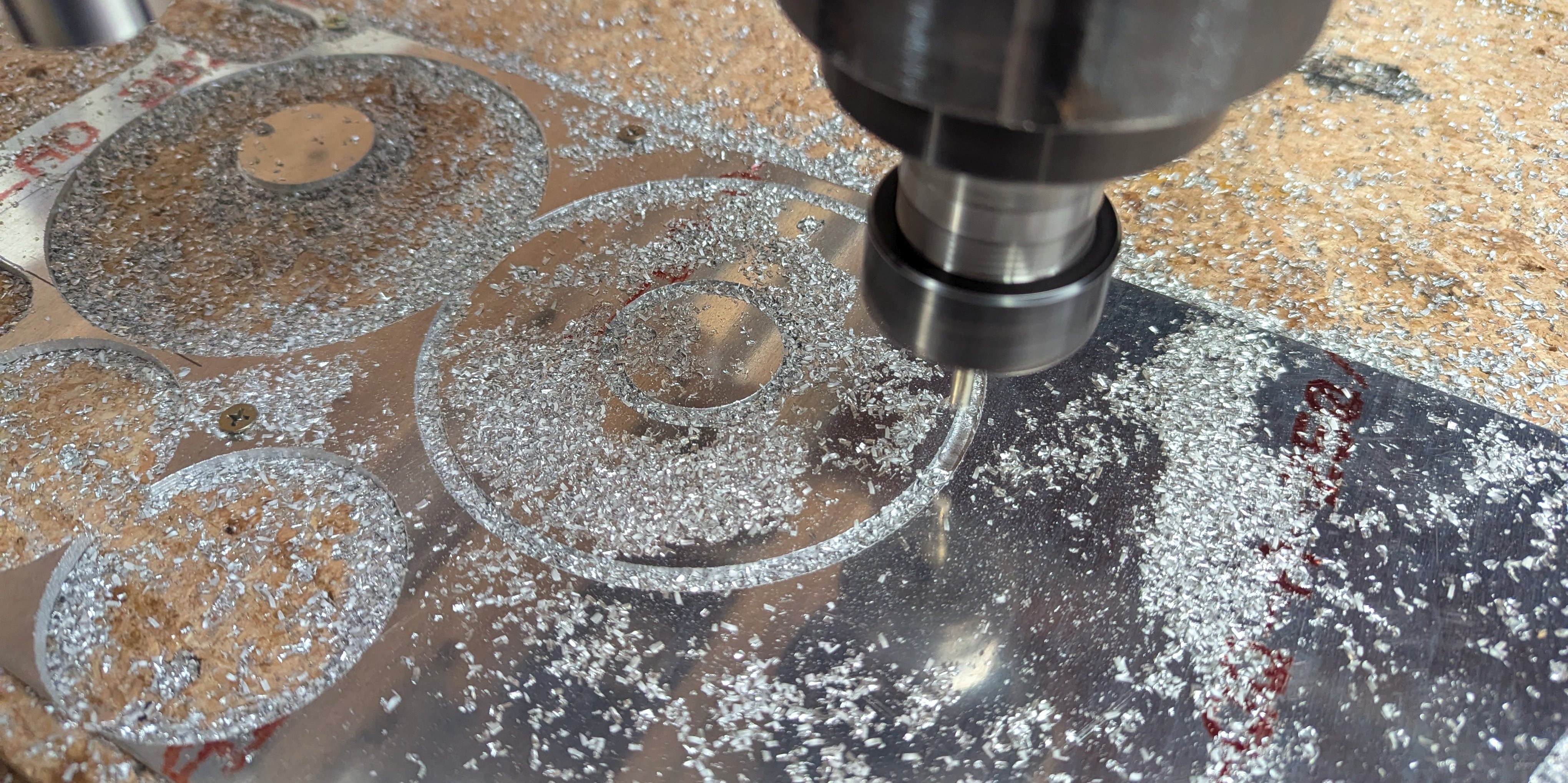
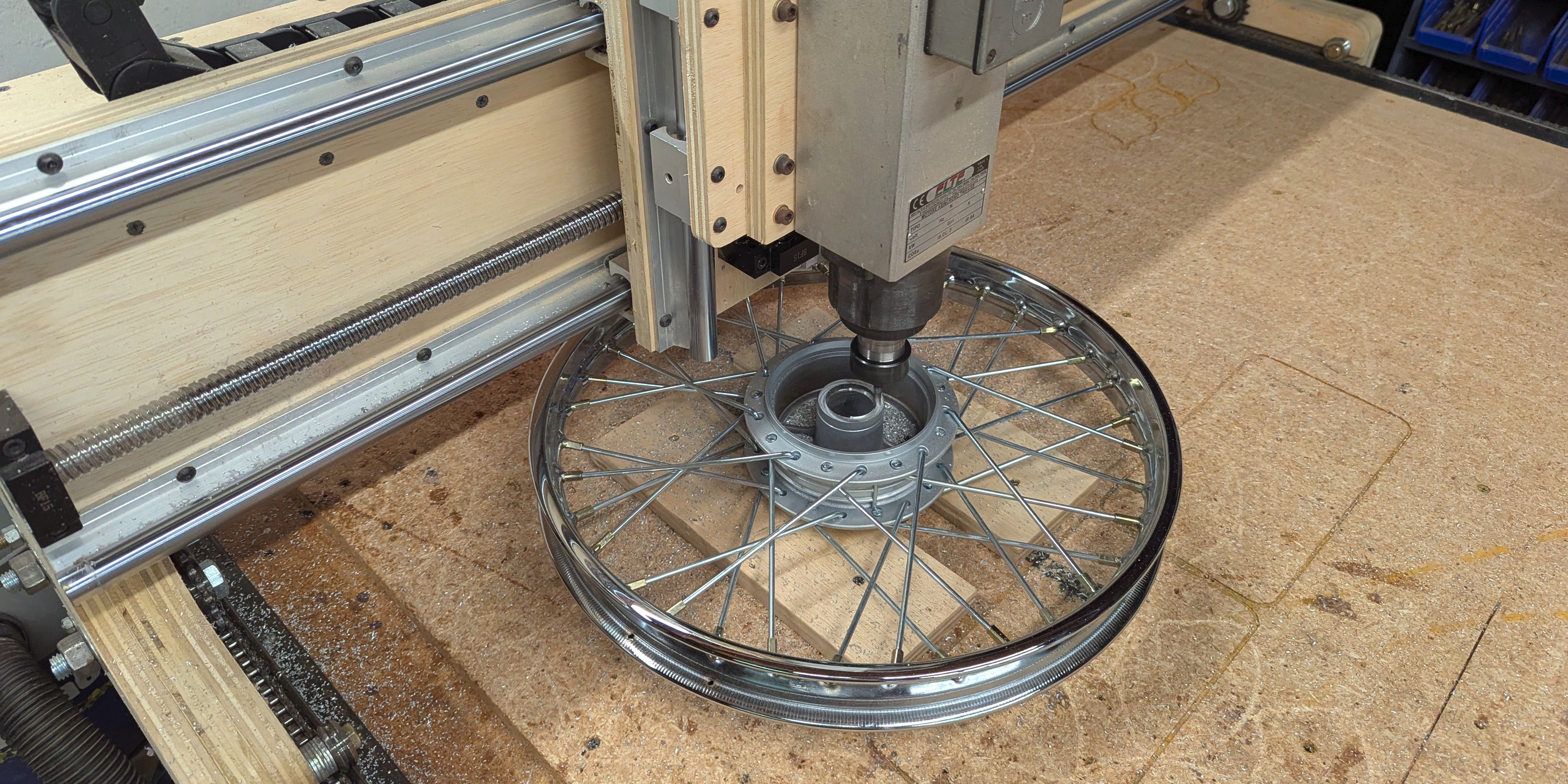
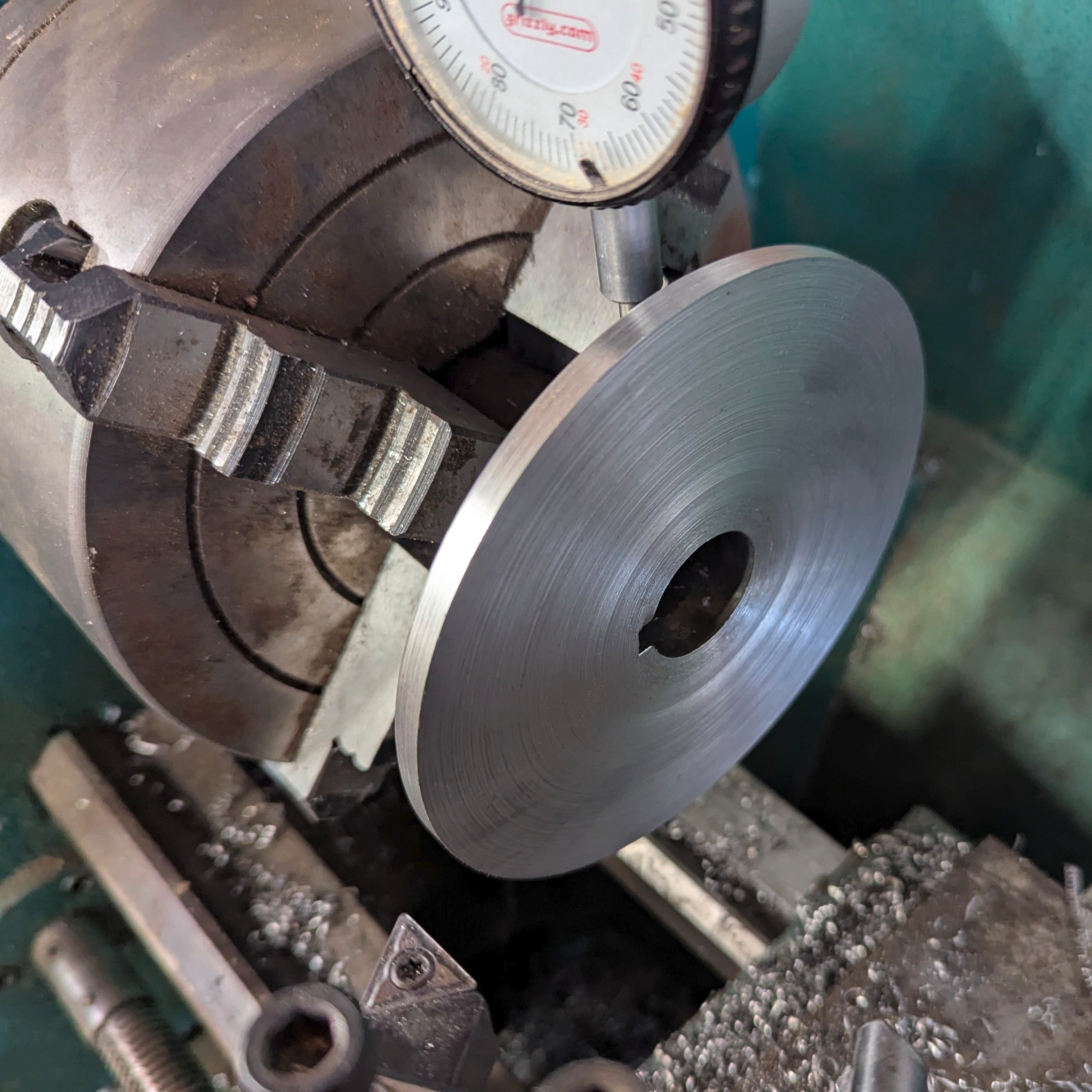
Mill out and remove the bearing center:
I simply milled it down with the CNC using an aluminum router bit. I took off 1 mm (0.040 inch) passes until the center was mostly gone (Well I did not, the CNC did. I started the program, shut the lights of the shop off, and came back an hour later). Eventually, both sides of the bearing center of both rear wheels were milled.


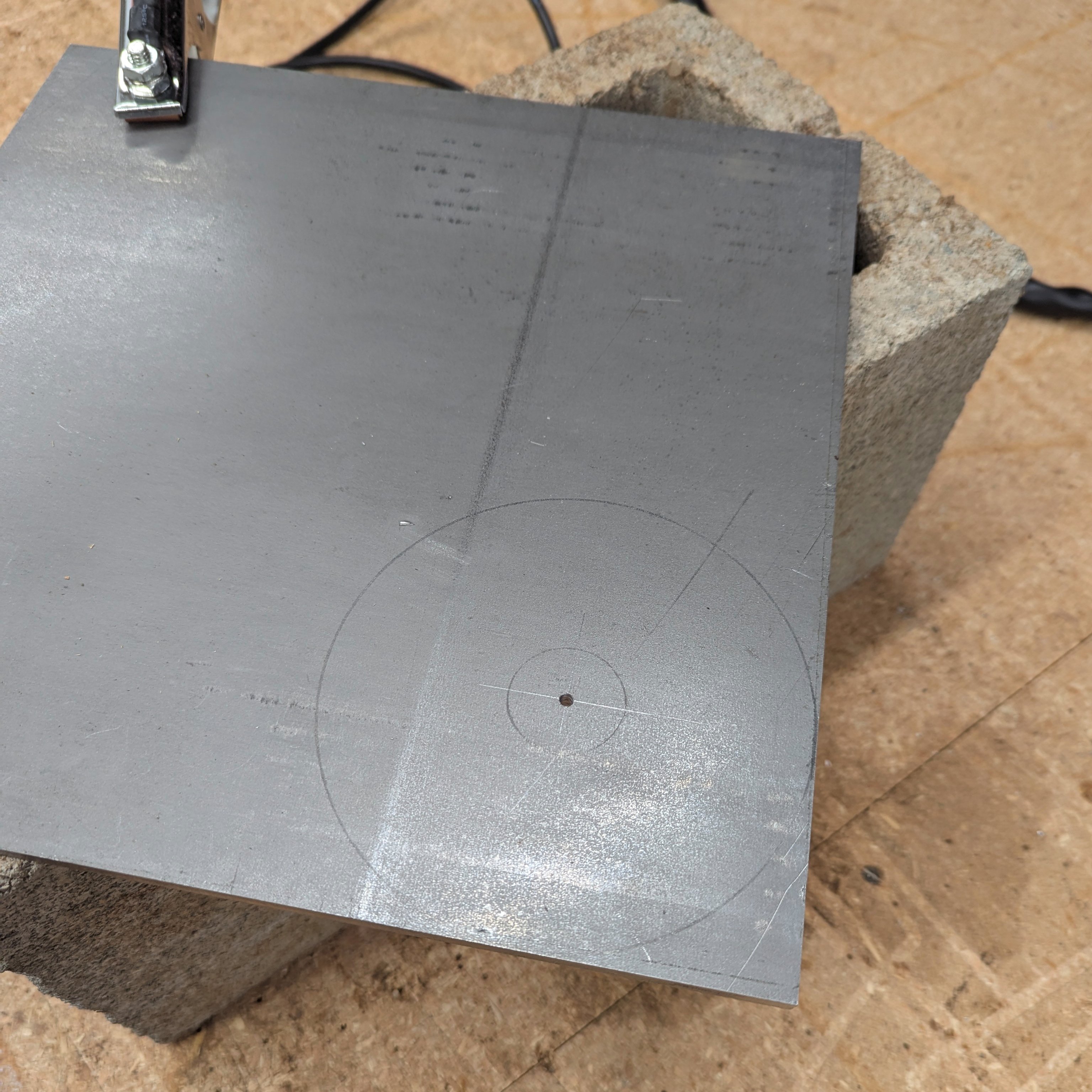
Cut an aluminum plate to support the outside of the wheel-hub:
I started with 1/2 inch aluminum plate. The outside profile, the fitted step, and the holes were all cut with the CNC. After this was cut out I had planned on finishing it on the lathe. But the CNC was accurate enough that all I needed to do was a little sanding.

Cut a steel plate to support the inside of the wheel-hub:
I used a plasma cutter to rough out a blank from 1/4 inch mild steel. The inside hole was finished on the lathe to match a steel weld-on hub (Azusa #8327). Then I TIG welded the two.
This assembly was put on the lathe to machine it to fit the wheel-hub.
This is the first reason to remove the spokes and rim from the wheel-hub. With the wheel-hub in hand, you can then see if this thing fits without taking anything out of the lathe!

The aluminum plate has bolt holes, but the steel plates do not. Not yet!
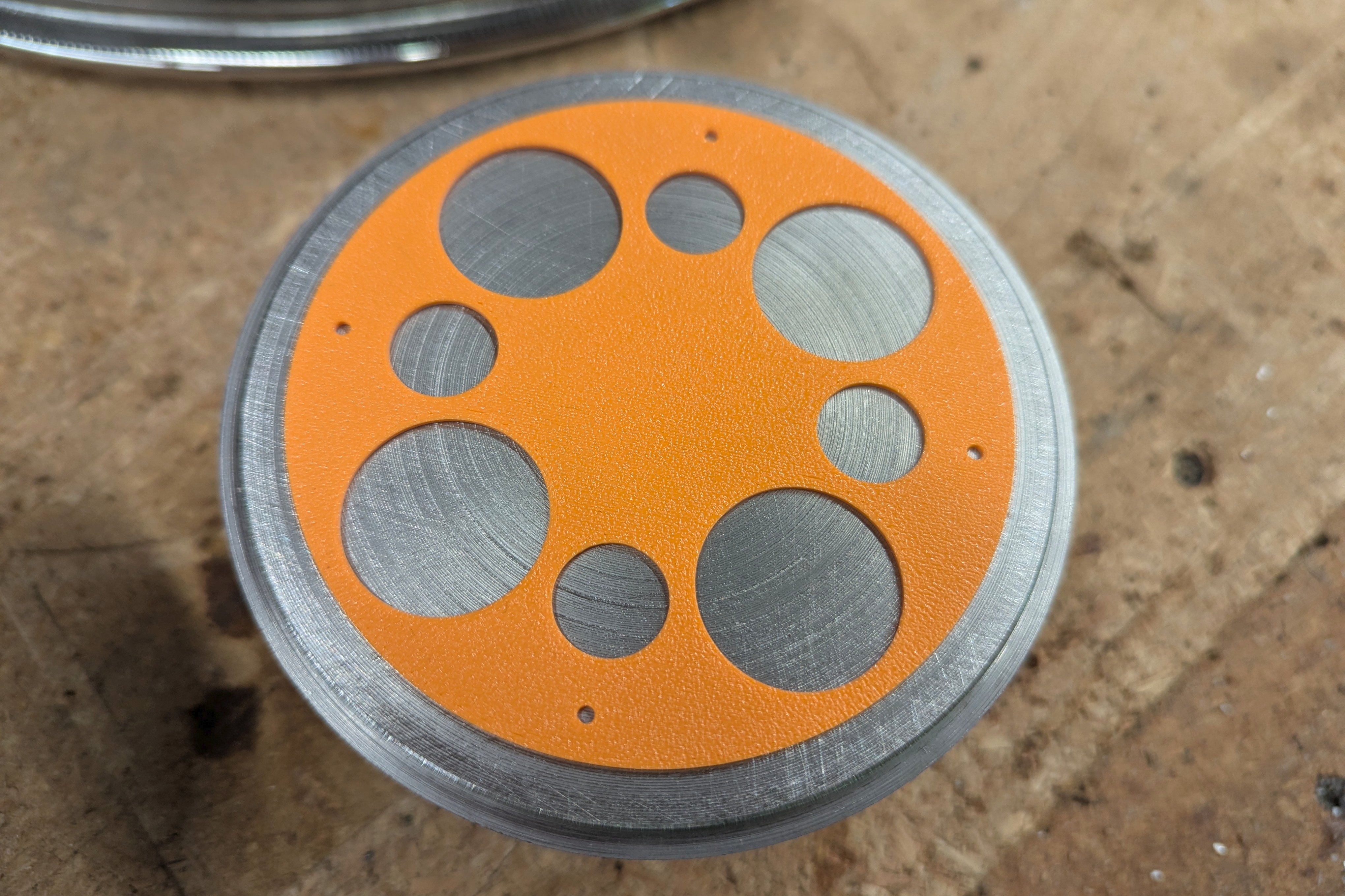
Print a 3D jig to locate the bolt holes.
My friend Barnaby told me that my 3D printer will be most useful as something that makes construction jigs for other things. He was right. As opposed to try to measure and mark the starting point for the bolt holes, it was just easier to 3D print a location jig.
The location holes are the four 3 mm holes near the outside edge. The other big holes are just there to minimize the amount of plastic used. The center boss fits exactly inside where the 1 inch shaft and 1/4 inch key would be.

With the 3D printed part snapped in place, I simply drilled four 3 mm center holes in the right locations, removed the jig, and finished the holes.
Match drill the bolt holes through the wheel-hub.
This is the second reason to remove the spokes and rim from the wheel-hub. My drill press (and Ernie's and Vince's) are just a little to small to reach with the rim still on.
It can almost reach! Just a little more... nope!

...So off came the spokes and rim!

The first hole is drilled very carefully. You can then mount the aluminum plate (it is on the bottom in this picture) with a bolt and this holds both the aluminum and steel plates in place. Get this first bolt alignment accurate and tighten it down. You can then match drill and bolt the remaining holes.


And that is about it.
Future Wheel-Hubs
With all of that fabrication work done, maybe on the next build...
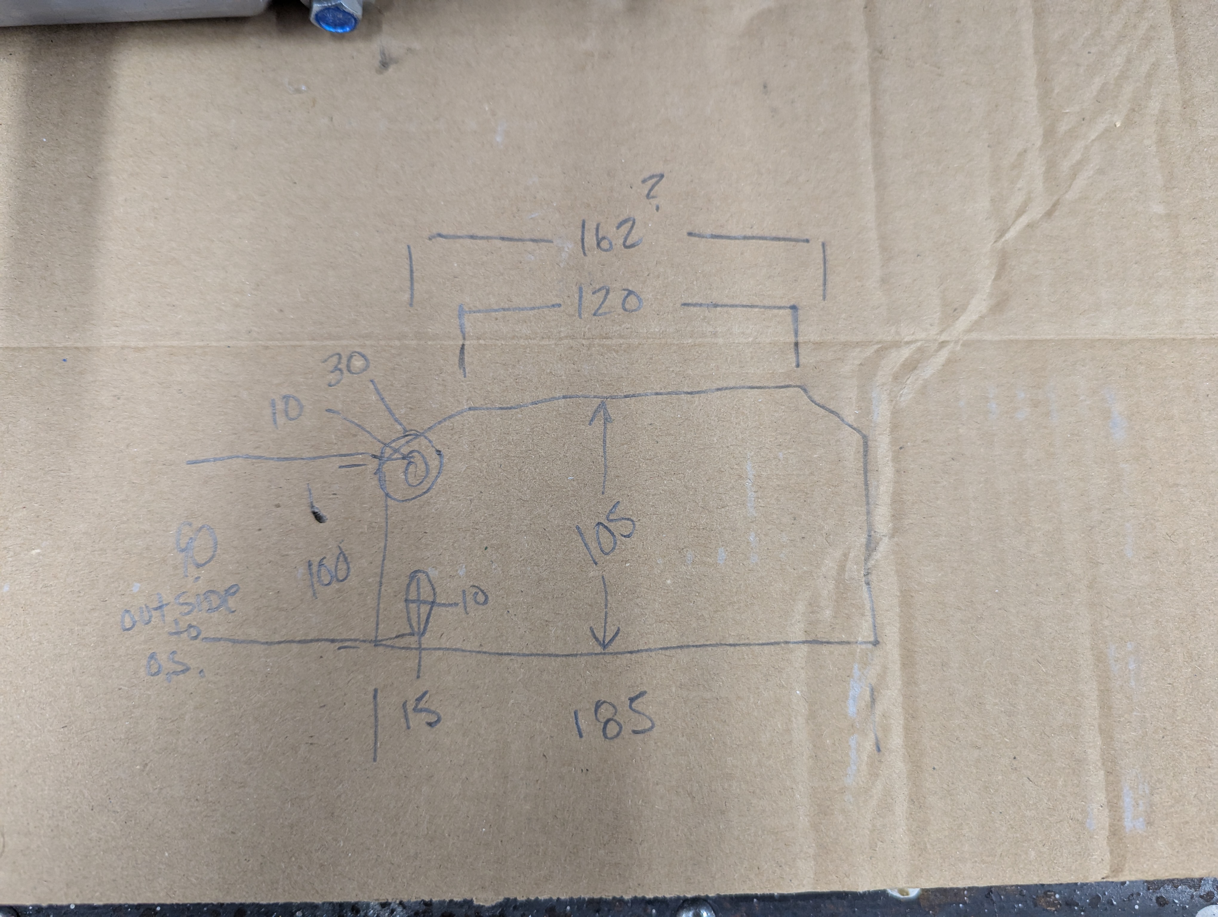
It might be easier to just build a wheel-hub from scratch. You only need two plates with spoke holes, a weld-on hub, and a center spacer. You do not need a big casting or to machine the whole thing from billet. The two plates can be similar to mine just larger and with 16 spoke holes, and the spacer can be cut from 4 inch steel pipe or whatever. It might be the same amount of work as trying to machine fit to an existing cast aluminum part. Just to remember for later:
There are four parts: Two plates, one on the inside and one on the outside of the wheel-hub. There is a weld-on hub in the center, and a spacer ring between the plates.
Parts:
- Start with a typical 1 inch steel drive shaft with ends that have a 3/4 inch threaded step.
- Use Azusa #8299 weld-on keyed hubs (1 inch ID, 1-3/8 inch OD, 2-1/2 inch long).
- Cut a 120 mm OD steel pipe spacer to 40 mm (or maybe wider).
- Cut two 150 mm diameter plates from 5 or 6 mm mild steel.
- Both plates shall have (18) 5 mm spoke holes on a 135 mm bolt circle.
- Both plates shall have a shallow recess or step to center the spacer.
- The outside plate shall have a center hole that close-fits the step on the drive shaft.
- The inside plate shall fit over the OD of the weld-on hub.
Why Metric?! Because it is a copy of a Honda wheel. Use Metric.
Assembly:
- Slide on the weld-on hub over the shaft.
- Bolt the outside plate to the shaft.
- Use this assembly as an alignment jig, double check for square.
- Weld the outside plate to the hub.
- Take this weldment off of the shaft.
- Position the spacer.
- Slide the inside plate over the hub.
- The spoke holes on the inside plate and outside plate should be staggered.
- Clamp the plates tightly against the spacer.
- Weld the inside plate to the weld-on hub.
- Weld the plates to the spacer.
HECK, while we are at it make front wheel hubs too! This way we can use larger bearings!
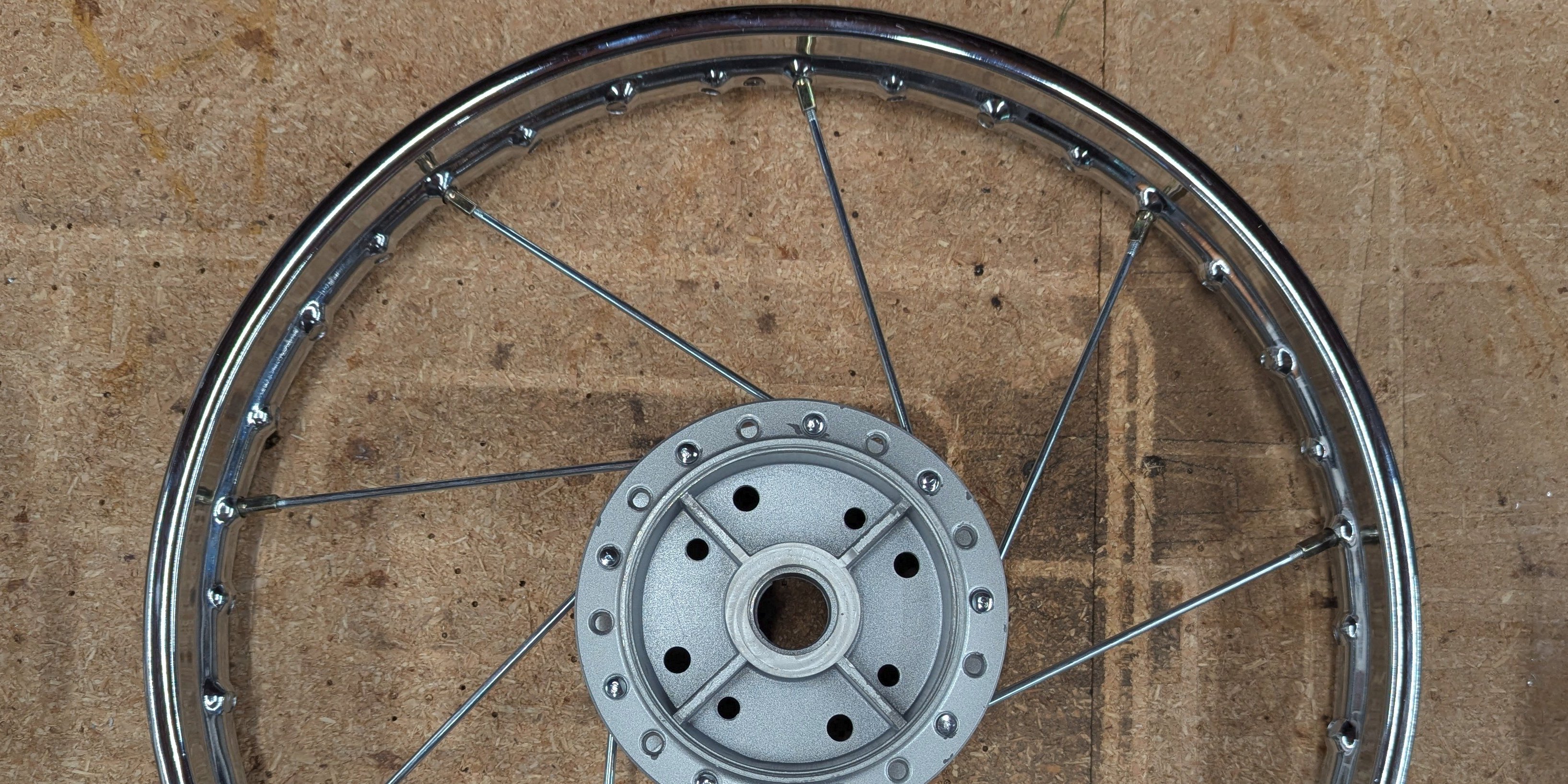
Lacing Spokes in a CycleKart Wheel
The rims obviously have holes for the spokes, but note that half point clockwise, and half point counter-clockwise. Half are on one side of the rim, and the half are on the other. Make sure when you lace the spokes they are connecting to a hole pointing in the same direction, and to a hole on the same side you are working on:

Step 1: Separate your spokes.
Outside spoke (left) and inside spoke (right):

Step 2: Lace the inside spokes on one side.
These are the spokes that poke through the outside and end up on the inside of the hub.
You get to choose if these angle clockwise (CW) or counter-clockwise (CCW). My goal is to have all four wheels the same, and since I already had two wheels with these spokes CCW that is what I did here.
Spokes are every other hole on this side of the hub, and every four holes at the rim. At this point, just position the spokes and put the nuts on with a couple of turns. All spokes should be very loose for the remainder of assembly.
Step 3: Flip the wheel over and figure out where to start.
When you flip the wheel over, the ones you did are now on the opposite side and appear to be angled the other way. Just remember that in the next step you are going to do exactly what you did in the previous: Lace the inside spokes angled the same direction you chose (for me that will be CCW again).
To find where you need start, you rotate the hub until the opposite side spokes are tight. Then you find a rim hole on this side pointing the correct direction. The spoke will line up with a hole on the hub.
You can see that one spoke in position at the top of the image below:
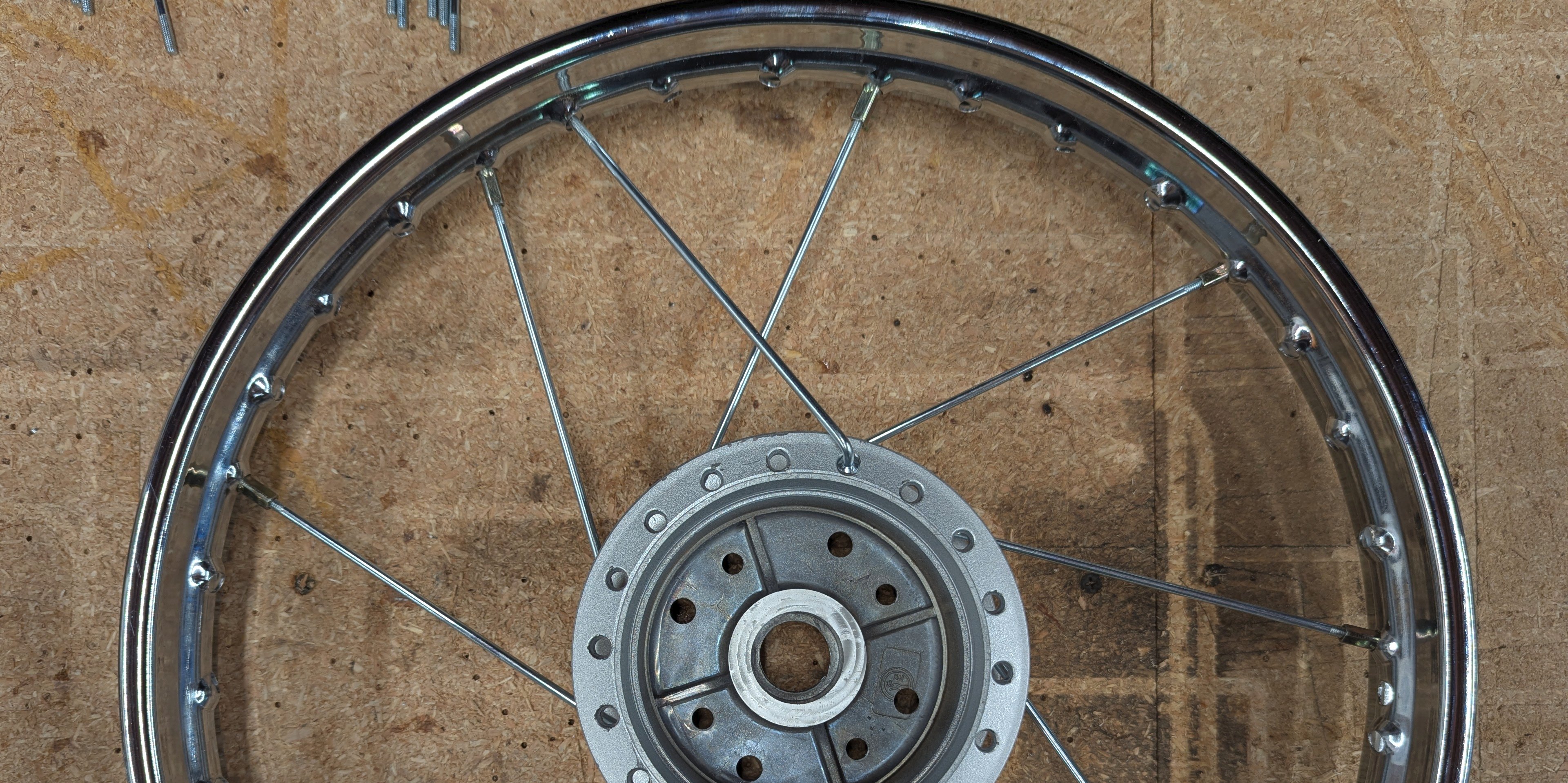
I have poked the spoke in that hole so I will not forget where to start:

Step 4: Rotate the hub to allow the remaining inside spokes to be positioned.
You can not get these inside spokes in place unless you bend something, or get the opposite side spokes to work with you. The trick is to rotate the hub (or the rim) so the opposite side spokes are angled the same direction you are trying to go with the spokes on this side.
So you rotate the hub, poke these spokes through, and then rotate the hub back all the while keeping these spokes on top of the opposite side spokes:


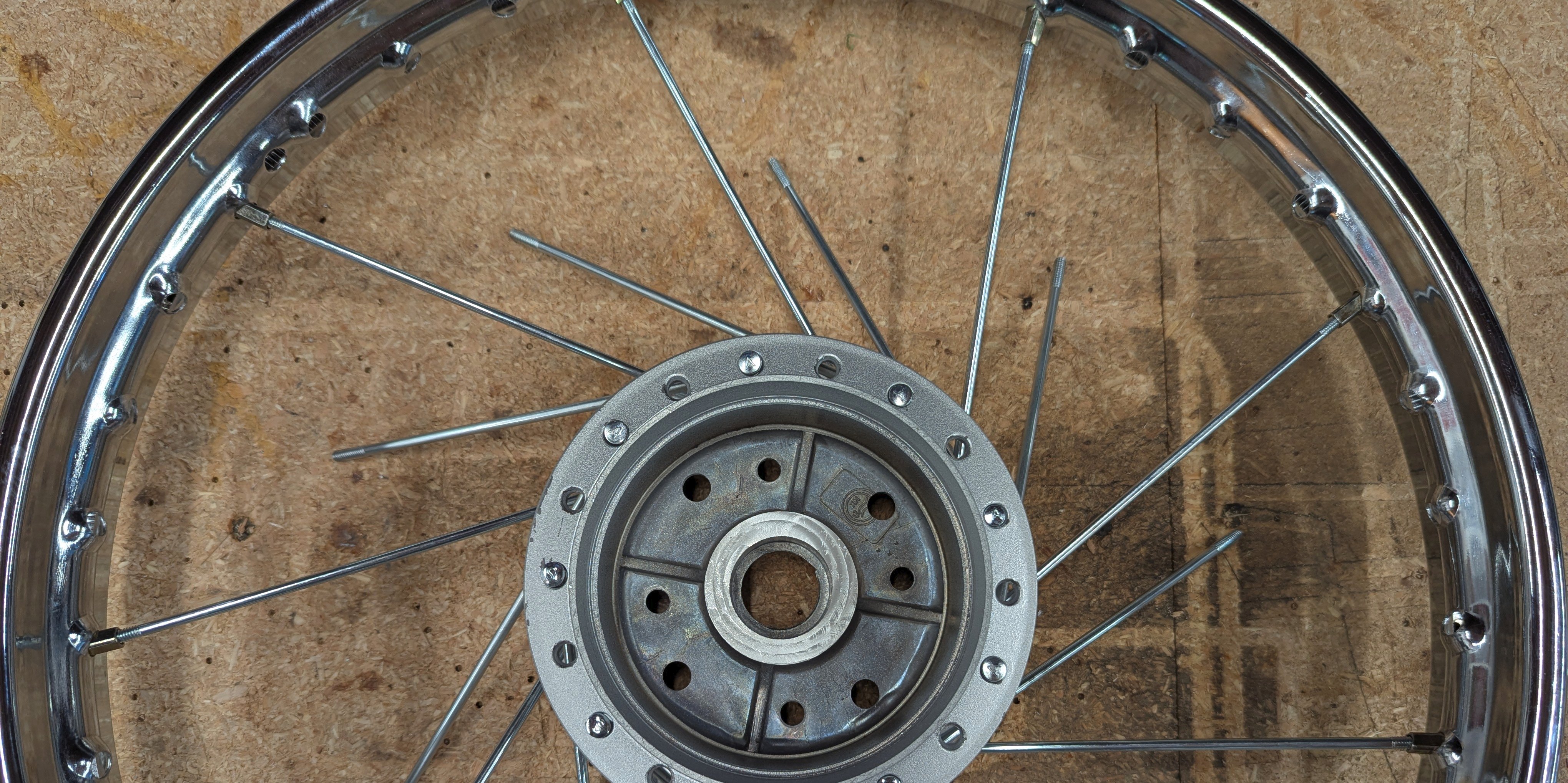

Notice the difference between the image above and the image below. Above the opposite side spokes are pointing the wrong way, and with a twist of the hub they are now back the correct direction as seen below (OK fine, I rotated the rim, same result):
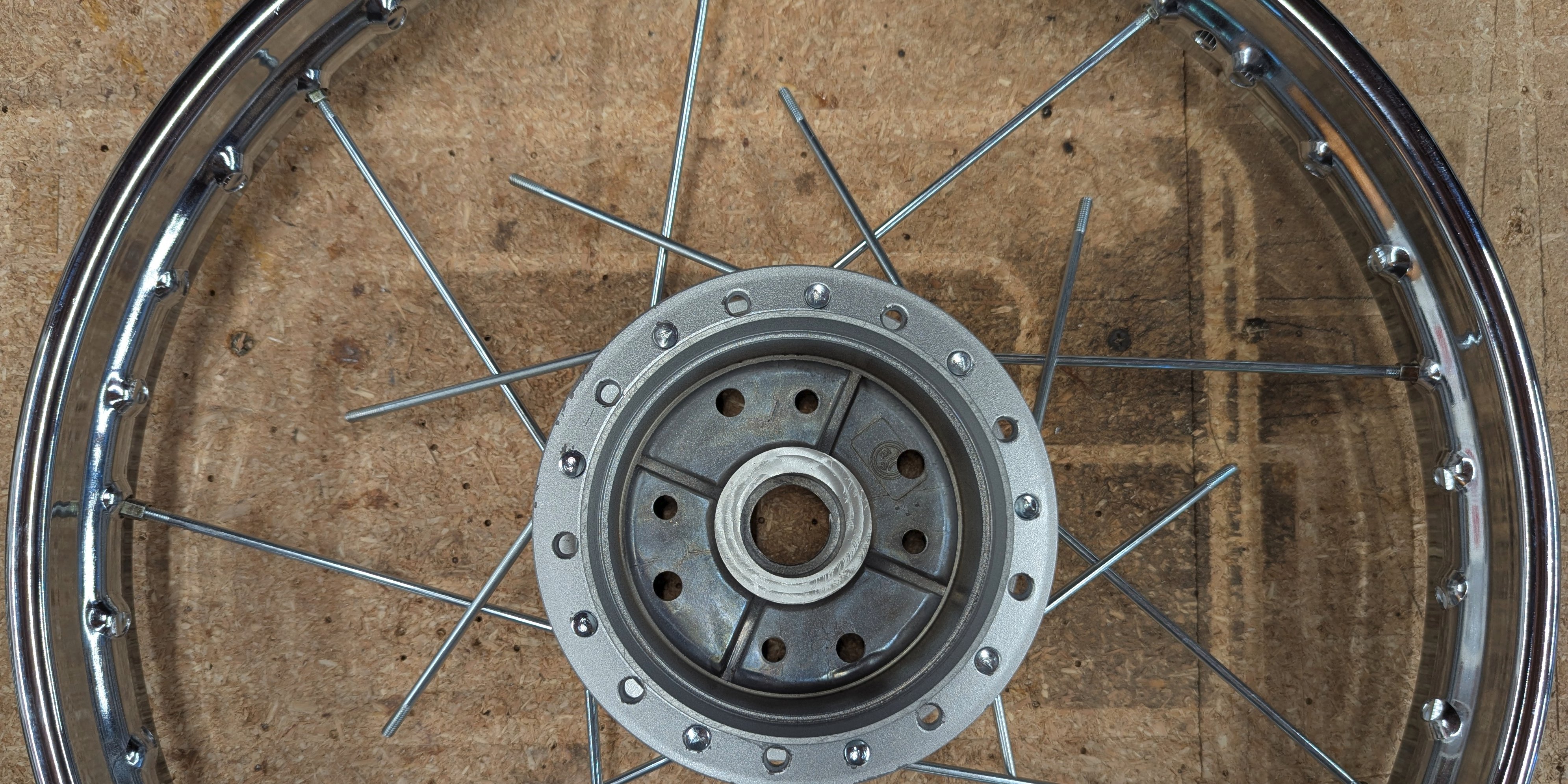
Then you just put the nuts on loosely. The inside spokes are all in:

Step 5: Install the outside spokes.
These are easy. Just poke them through in any order in every remaining hole and connect them to the rim. They angle the opposite direction of the inside spokes on this side of the wheel.

All spokes installed:
Then you tighten the spokes and straighten the wheel (you can figure that out, right?)
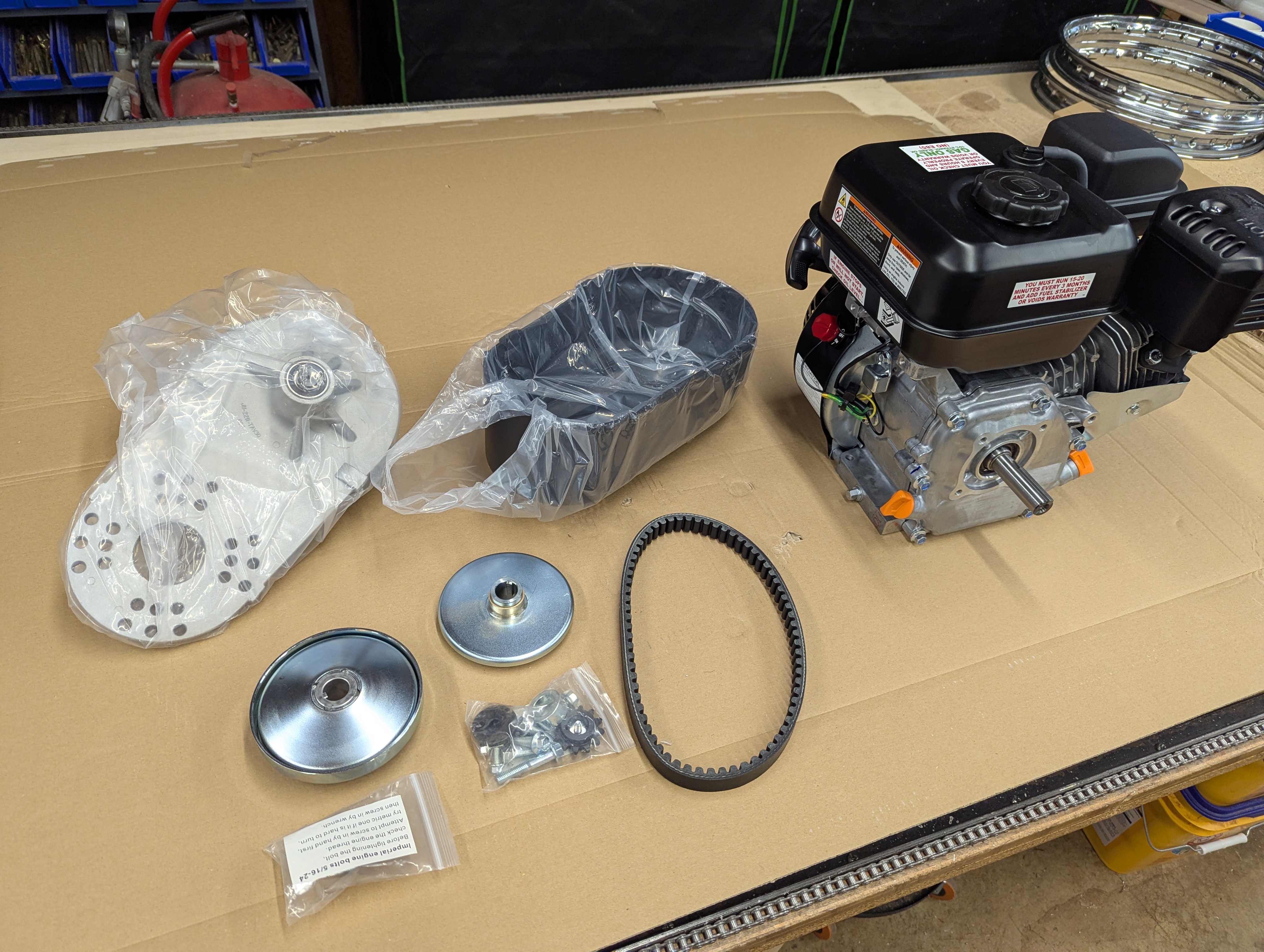
Engine
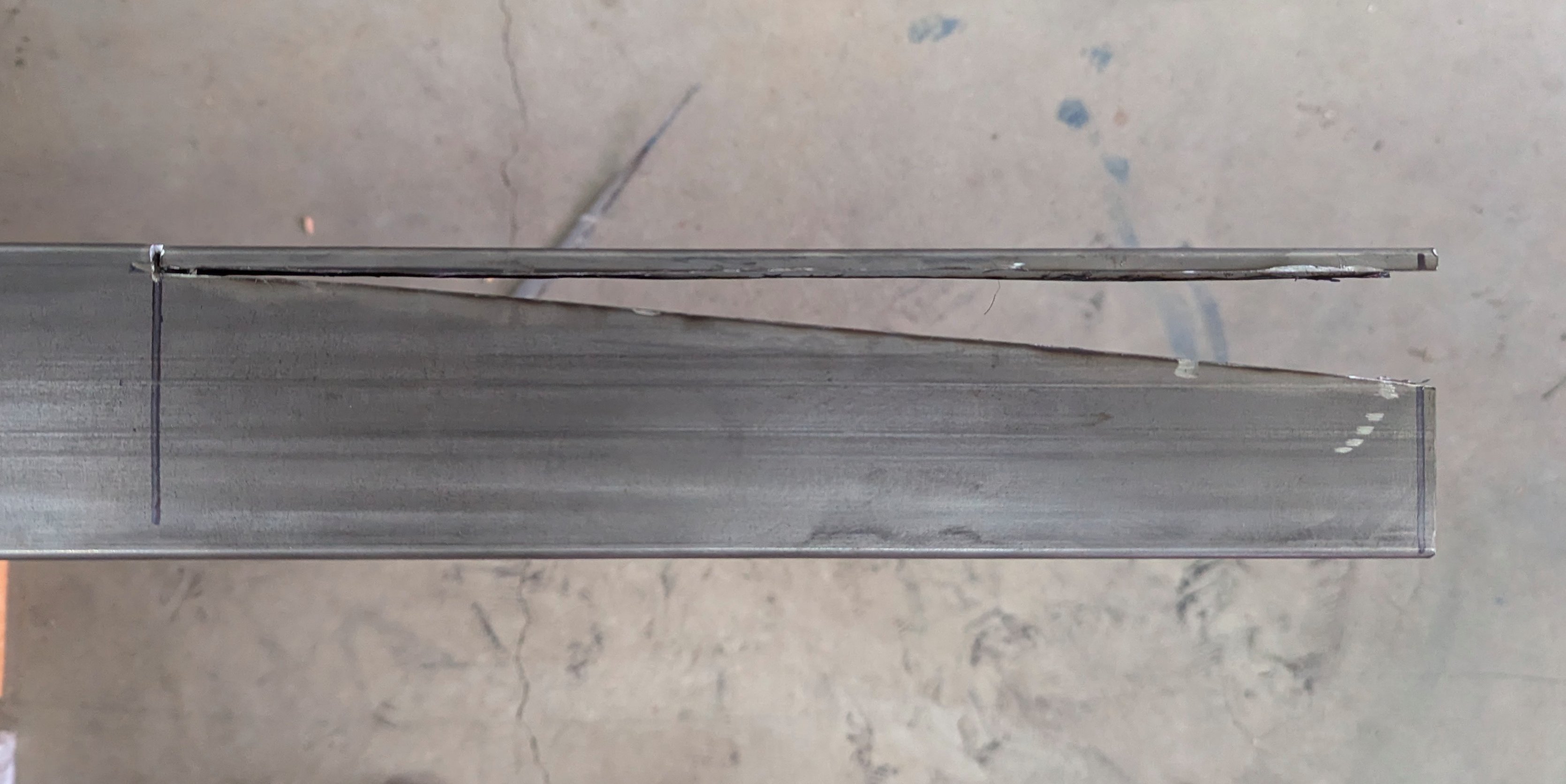
Ernie's Frame


Keep building!