Experimental Aircraft Fuel Injection and Engine Control Unit
Specifically for experimental homebuilt aircraft, I created a custom ECU, wrote custom firmware, installed fuel injection, and allowed the ECU to control the spark. This page details those efforts.
The following historical information is provided as a reference. It details how I got to where I am, but should not by itself be considered as a guide. Eh, it is a fun read but useful only at this point for entertainment.
If you are interested in the current progress of this project, it is here:
Experimental Aircraft Fuel Injection and Engine Control Unit
The original development of this project was broken into three parts:
-
Getting an engine working with the MegaSquirt ECU and MegaSquirt firmware.
-
Getting an engine working with the MegaSquirt ECU and custom firmware.
-
Getting an engine working with a custom ECU and custom firmware.
That is all detailed below...
- Experimental Aircraft Fuel Injection and Engine Control Unit
- Installing a MegaSquirt EFI engine control unit and a Harley Davidson throttle body on a Corvair engine
- Custom Electronic Fuel Injection (EFI) Engine Control Unit (ECU) for the Experimental Aircraft Corvair Engine
- Custom Firmware, First Iteration
- Custom Controller, First Iteration
- INJECTOR
- MANIFOLD AIR PRESSURE (MAP) SENSOR
- MANIFOLD AIR TEMPERATURE (MAT) SENSOR
- THROTTLE POSITION (TP) SENSOR
- IDLE AIR VALVE
- OIL TEMPERATURE SENSOR
- Lesson About Grounding and a Good Battery
- The Video of the First Run (MegaSquirt with Custom Firmware)
- Abandon MegaSquirt and Abandon the First Custom Controller
- Arduino based Electronic Fuel Injection (EFI) Engine Control Unit (ECU) for Experimental Aircraft
- Trigger Wheel Experiments
Installing a MegaSquirt EFI engine control unit and a Harley Davidson throttle body on a Corvair engine
[Originally written in 2008]
CORVAIR EFI ENGINE CONTROL
As part of my project to convert a 1965 air-cooled Corvair engine into an experimental aircraft engine, I have been working on building and setting up an engine control unit (ECU) to control the electronic fuel injection (EFI) and the ignition timing. This part of the project was as difficult and time consuming as the physical engine assembly.
ENGINE CONTROL UNIT
The control computer is a MegaSquirt kit. I used the MegaSquirt II controller with the Version 3.0 control board.
Because the MegaSquirt ECU is an open source project (just a bunch of guys on the internet getting together to build these things) the ECU came as a kit. Also, to test the board I first had to build a Stimulator which was also a kit. The Stimulator provides user controlled engine signals to the control board so you can test the board and initially set up the control code.
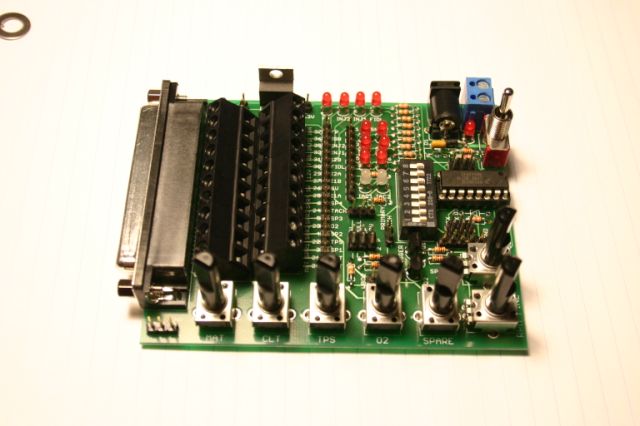
The Stimulator is the first to get constructed. There are two variations of this Stimulator available, I got the more complex and more expensive one.
Stimulator complete.
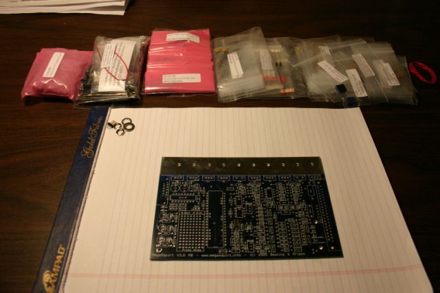
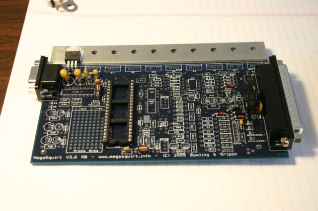
And now I can start on the controller.
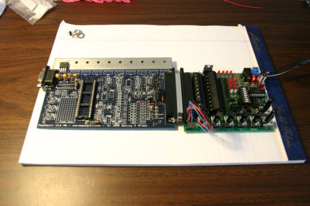
The partially complete controller and completed Stimulator are connected to each other for testing. Notice how this happens long before the majority of the components are installed on the controller. The steps are "install this, test it, install that, test it" and so on.
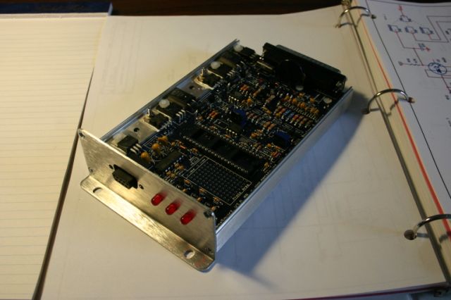
A few pictures of the completed controller. The whole project took a week or so of evenings to solder all the parts together. It was way too cold outside to do real work anyway.
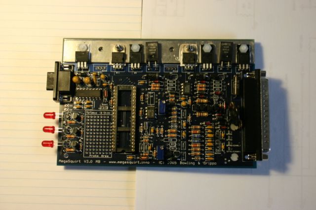
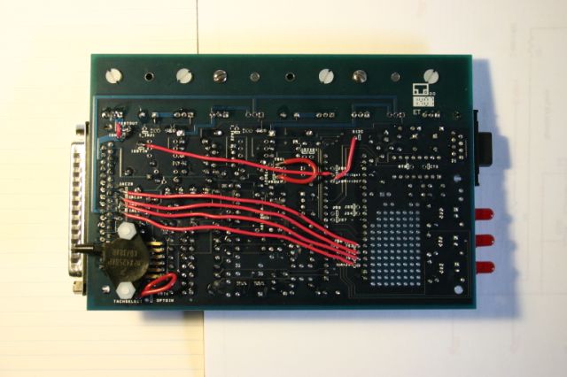
MegaSquirt ECU complete.
ASSEMBLY NOTES AND SUGGESTIONS
There is going to be a lot of soldering of small components. This will be somewhat different than soldering wire together in your car stereo, primarily because the items are smaller, need to be grounded, and are sensitive to heat. I used a grounded 15 watt soldering iron; it doesn't have to be any bigger than this and it needs the ground plug. I also used standard electronics rosin core solder (60% tin / 40% lead) that was 0.032" diameter. This comes in 0.050" diameter, but this is a little large for micro-component work. To unsolder mistakes, I needed some de-soldering wick (its a fine copper wire braid that press between the bad solder and the iron and it sucks up the solder).
Since I have a newer computer, I had no serial port. I did use a cheap $20 USB-to-Serial adapter that, regardless of the name on the box, was a Prolific adapter.
The MegaSquirt can be configured for a variety of setups, so you have to know what equipment you plan to use (like injectors, if you plan to control timing and how, etc.) because there are a couple of different wiring options on the board. Here is what I plan on doing:
- For engine speed, I will use a 36-1 missing tooth wheel with a VR sensor.
- I plan on using narrow band O2.
- I initially plan on using the MAP sensor on the board.
- My throttle body has a PWM idle valve and I installed the on-board components.
- I will control the coil directly; I installed the high-current ignition circuit.
- The injectors are high-impedance and I did not install the PWM flyback circuit.
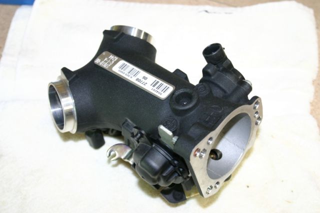
CORVAIR-HARLEY THROTTLE BODY
Harley Davidson has been providing all of their motorcycles with fuel injection throttle bodies for several years. You can no longer get a factory Harley (or Honda, Yamaha, etc.) with a carburetor. This great thing about this is that there are those who will remove the fuel injection system to put a carburetor back on or upgrade the stock throttle body to one that is larger. This means that you can get what I got on EBAY for $99.
A Harley throttle body is sized for engines in the 100 horsepower range. This means that the intake and outlet diameters and the injector flow rates are all PERFECT for a Corvair.
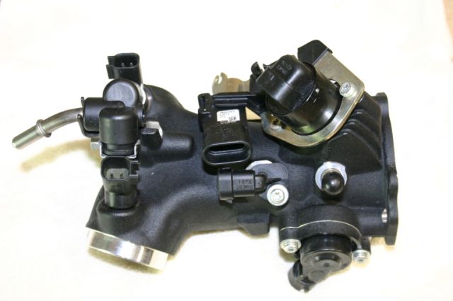
Here's the cool part... look at the design: If you mount it under the Corvair engine and place it upside down, it already has two outlets that turn up a little. This is perfect for two intake runners routed up to the two sides of the engine. It also has a front flange ready for a Harley aftermarket air filter. So there will be no modification required for this body to bolt this to a typical Corvair conversion intake.
Here's a second really cool thing... all the sensors, injectors, and even a throttle cable attachment are included! From the pictures below, you will see (from right to left):
- The flanged intake
- The throttle plate with return spring and cable mount
- The throttle position sensor
- The idle air valve
- A hose fitting for a prime injection or a remote pressure sensor
- The outside air temperature sensor
- The manifold absolute pressure (MAP) sensor
- Two injectors, one each side
- The fuel connection tube
- Two outlets
- And the whole thing weight a pound or two
The only other sensors needed for a fuel injection system are the crankshaft position sensor (which will provide engine RPM) and the O2 sensor. Both of which are easy enough to find at AutoZone.
It's a bit difficult getting specifications for these sensors since Harley is really secret about their products (it forces you to go to a dealership). However, all of the sensors are Delphi and if you search the internet all week long, you can find what you need. I even found a source for appropriately priced connectors for the sensor fittings. If you look at my Master Checklist, I have the part sources and injector flow rates listed in the notes.
TRIGGER WHEELS
To generate an RPM input, I started using a 36-1 trigger wheel and a VR sensor. I had planned to put that on the rear of the engine. The Corvair harmonic balancer is about 6-3/4" diameter which means I need a pretty large wheel to stick out further than that.
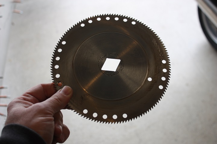
The design is based on using 1/8" (plus or minus) steel sheet, or just an old 10" table saw blade, and gluing the template on with spray adhesive (such as with 3M Super-77). The recipe: punch, pilot drill, and drill all the holes; rought cut the diameter down to size with a bandsaw; cut the teeth out with a band saw; finish the diameter with a lathe, and smooth off the burrs with a file.
I had a piece of 12 gauge sheet (0.105" thickness). In about an hour and a half, I had it roughed-out and this is what I had:
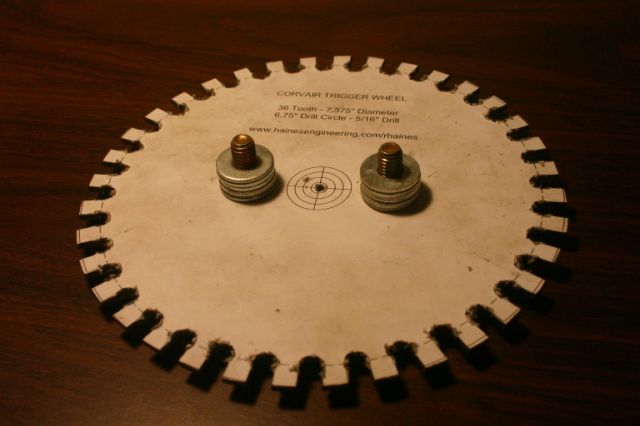
I plan to bolt it on using the pulley-puller bolt holes. I stacked washers so that the wheel stands off of the balancer a bit and to also keep the bolt threads from contacting the oil seal on the other side. The threads showing should be about 3/8"; at 1/2" you hit the oil seal. I will eventually replace the washers with stand-off ring.
OK, plans change...
I am now using the flexplate with slots cut in it for a trigger wheel. To the left at the 9 o'clock position you can see one spoke missing that will act as the "missing tooth". I calculated and drilled holes on the opposite side to keep things in balance.
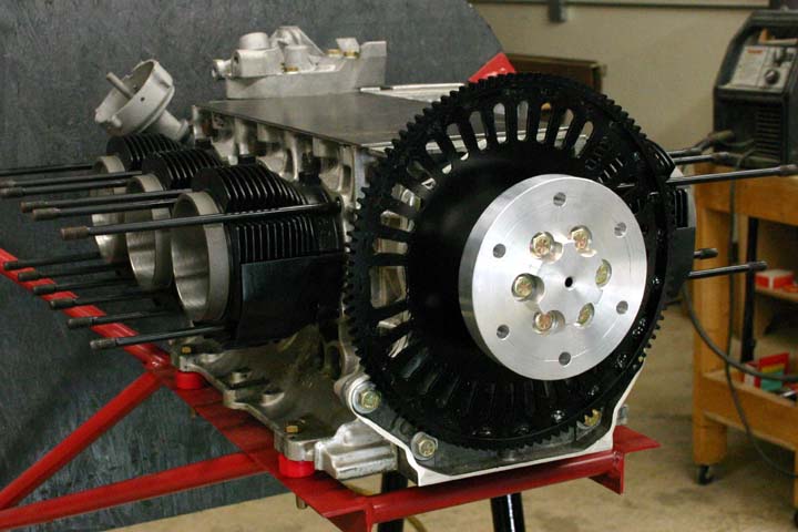
Also, I didn't just cut out any tooth... I cut out the tooth that lines up with the #5-#6 rod journal. This way, I know where the damn thing is and I can index my propeller so that they are not lined up. Of course, I will use the settings in the software to adjust the timing (i.e. set the first spark to be some number of teeth or some degrees after the missing tooth; I couldn't be so lucky that that lined up too).
OK, plans change again...
When I tried to get it running, I had a real hard time getting the computer and the engine to synchronize with each other. With a missing tooth wheel, the software starts looking at teeth passing by and estimates a window of time when the next tooth is to be seen. If the next tooth isn't seen in that window, it is considered the Missing Tooth and it then knows where the crankshaft is. The problem I had, partly because I'm using a wimpy starter and partly because I have no large flywheel, is that I couldn't get a few smooth rotations to allow the computer to correctly see the missing tooth. The crank would slow down in spots and the computer would start falsely seeing "missing teeth" only because the actual teeth were late in the window of time. As opposed to trying to get the missing tooth wheel to work, I just made it easier on myself:
I replaced the missing tooth wheel with a wheel with only three teeth. This is the same input that would be generated by electronic points running within a distributor. I then told the computer to forget trying to sychronize with a missing tooth wheel and just to spark when it sees a tooth. Well, actually it's not looking at teeth, but holes in the flywheel.
This is the wheel that I got the engine running on. It has only three holes and they and the sensor are lined up with 0 degrees TDC of each pair of pistons. Although I have to think about it, I can figure out where TDC of #5 and #6 are so I can index the prop.
I also made the holes so that the hole starts at TDC and ends at 20 degrees after TDC. Megasquirt allows you to choose between firing the spark during Cranking (not Running) either with an advance calculated from the tables OR based on when the input trigger "rises" or "falls". If I select "rises", it will fire the spark at TDC. "Falls" will fire it at 20 degrees retarded. I'll work through these options to see which works best.
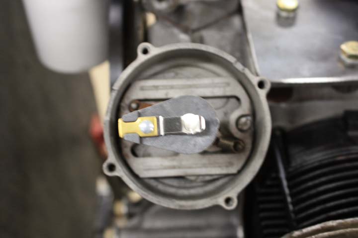
One other thing about this arrangement. Since the computer doesn't synchronize with the crankshaft, it doesn't know which spark plugs are firing so it can't run a distributorless system (such as coil packs or coil-on-plug systems). I am using a distributor, but only the rotor and cap. The points, springs, weights, and vacuum advance were taken out. Well, more about that on the next topic...
IGNITION
The MegaSquirt ECU is used to energize and control the primary circuit of the ignition coil. Based on a detailed table, the ignition is timed based on RPM and manifold pressure. To keep things relatively simple, the ECU is asked only to provide three evenly spaced sparks for every crankshaft revolution (two crank turns for every cycle, six cylinders, you do the math). The distributor is used to send the sparks to the correct cylinder. Simple, eh?
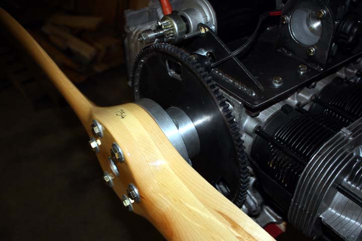
On a Corvair, the distributor rotor points to the 9 o'clock position (straight left) when the #1 cylinder is at top dead center. Since I have the ECU controlling timing and there are no points, I can just bolt down the the distributor with the cap over the rotor in this position, right? Nope.
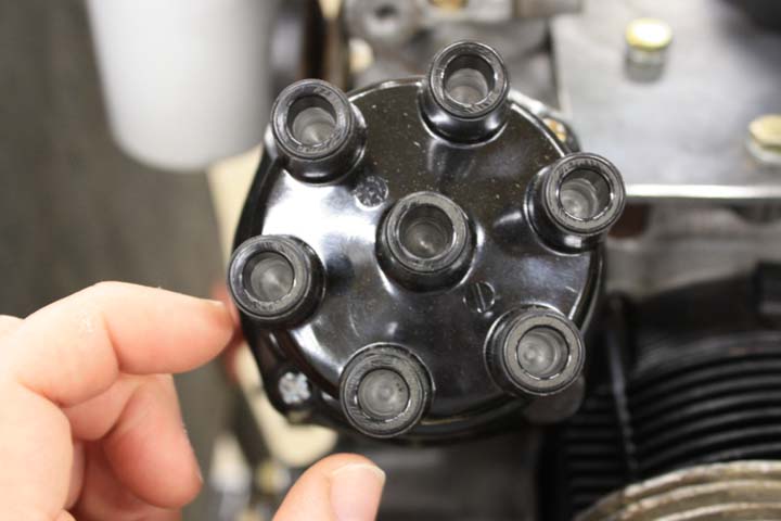
With the #1 terminal at the 9 o'clock position, the rotor and cap line up and would be perfect if I only planned to set my ignition at 0 degrees. Since timing is generally advanced, the distributor needs to be advanced a little (turned counterclockwise) so that the rotor and terminal are always in reach of each other to transfer the spark. In the picture below, my finger points to the #1 position. If I set the cap here and set timing to 60 degrees advanced, the spark would go to the #6 cylinder which is where my thumb is pointing to.
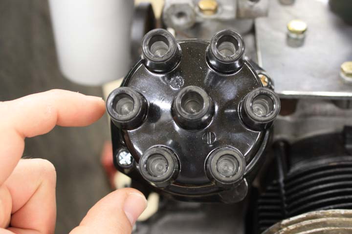
Knowing that my ignition will typically range from 0 to 30 degrees, I need to advance the cap about 15 degrees so that the cap and the rotor align in the middle of this range. Since the angle between the #1 and #6 terminal is 60 degrees, I turned the rotor so that #1 moves 1/4 of the way to the #6 position.
By the way, the firing order is 1-4-5-2-3-6 clockwise with the actual #1 cylinder adjacent to the distributor (seen in the picture above) and the #2 cylinder on the opposite side.
WIRING
The detailed wiring schematic is obviously available from the MegaSquirt website so I won't go into those details here. However, there are a few wiring details which are specific to this installation that you won't find anywhere. Interestingly enough, one of the most time consuming items on this whole engine build was figuring out which damn connectors to use! I probably at least spent a full week of eight hour days looking at manufacturer's parts drawings, websites, and Mouser.com to get where I am now.
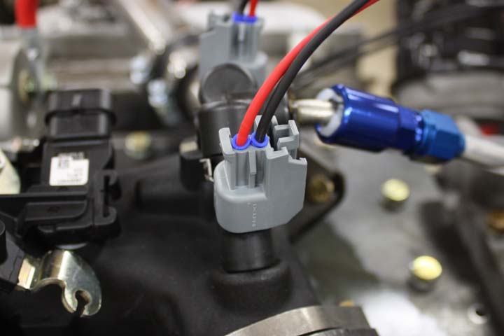
The majority of the connectors used on the sensors of the Harley throttle body are "Metri-Pack 150 series". Metri-Pack is a OEM standard (or it's a Delphi product that everyone copies) and the 150 means that the pin width is 1.50 mm in width. If you Google "Metri-Pack" you will get several distributors whose websites provide very detailed pictures. You can get several styles of the 150 series... all of the connectors used here are "sealed" (meaning a little rubber seal keeps water out) and most of them are "Pull to Seat".
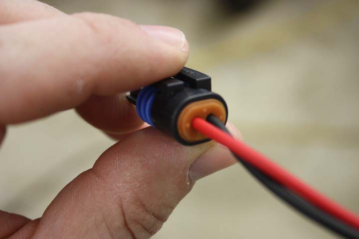
The "Pull to Seat" is a style of pin design that locks the pin in the connector by pulling it backwards into the connector. So what you would do is feed the wires through the back rubber seal, then through the connector, then install the pins (crimp and/or solder), and then pull the wire and pin back into the connector where it lock into place. The rubber seal is then pushed in the back of the connector.
This style is generally used for sensors with an integral male connection; only the female "Pull to Seat" connectors are available as kits or as pigtails from supply houses. The throttle position sensor, intake air temperature sensor, oil temperature sensor, idle air valve, and my first VR sensor all had this style of connector. Commonly, the Pull to Seat style has an integral rubber seal on the back:
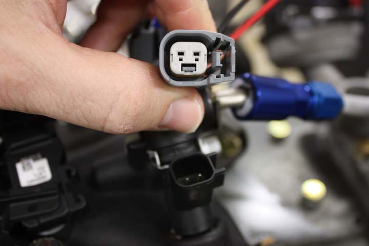
the other style of the Metri-Pack 150, which I guess is the standard connector, is notably different. The pins are the same size but a different style. And the wire seals do not come with the connector. But, the connectors are available in male and female versions so they are handy when you need to add a connector to a sensor the comes with unterminated wires (like the O2 sensors or the Hall sensor used for RPM).
You can see below the separate seals common to the Metri-Pack 150 series which are NOT Pull to Seat:
The final exception are the injectors, which are "Metri-Pack GT-150 series". Confused yet? I was. I'm sure there was some Delphi engineering manager that came up with all these styles just to keep his department in work!
the Metri-Pack 150 series is good for 14 amp continuous. MegaSquirt recommends 18 gauge wiring for everything; it's a little conservative but considering that some of the runs might be long, that's what I went with. I also made sure I ordered automotive accessory wire that was rated for engine compartments (Summit SXL)... I ordered a 100 foot roll of black and one of red and had plenty. I probably should have ordered a roll or blue for the sensors that have "power", "ground", and "signal".
You need to know your wire size when ordering the Metri-Pack connectors because there are different pins and seals available for different size wires. To make it worse, the pins and seals are cataloged for metric wire. A 18 gauge wire is about equal to a 0.75 mm2 metric wire (18 gauge is about 1.02 mm in diameter with a cross sectional area of about 0.8 mm2 and 6.6 ohms per 1000 feet of resistance). This information will be necessary for selecting the pins. The insulation diameter will be needed for selecting the wire seals.
I got all of my connectors from Mouser Electronics under Interconnects > Automotive Interconnects. It would be great if all the connectors were the same; the air intake temperature, the oil temperature, and my first VR sensor were all two pin... but were they the same Metri-Pack 150 Pull to Seat two pin connector?! Hell no. One had the catch on the side, one was upside down, what a pain in the ass. The nice thing about Mouser is they provide a picture of the part. And if that's not enough, they provide a link to the manfacturer's page for that connector. And if that's not enough, the manufacturer provides a link to the engineering drawing. So if your sensors and injectors are not the same as my sensors and injectors (of which part numbers are already found and listed in my Master Checklist)... GOOD LUCK!
Finally, the connector for the MegaSquirt is a typical DB-37 (DC-37, whatever) which are made for soldering 20 gauge wires to. Since a 18 gauge wire doesn't fit into a 20 gauge hole, I had to trim the wire a little. After I stripped the wire, I would snip the end at a sharp angle to create a point and this would fit into the pin hole a bit better. This also begs the question why we are using 18 gauge wire... A pin on the DB-37 is only rated for 5 amps and the actual pathway on the printed circuit board is even smaller yet, so 18 gauge seems overkill. Whatever.
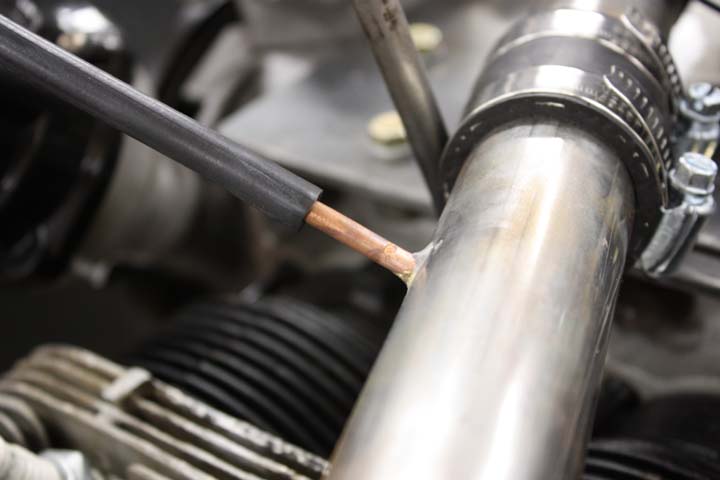
OK, so this isn't wiring, but its a MegaSquirt connection... The standard manifold air pressure (MAP) sensor is located on the MegaSquirt board. You connect it to the manifold using some vacuum tubing, like can be seen in the picture below. I've simply brazed a piece of 1/8" tubing on to the intake runner. The Harley throttle body has a MAP sensor integral to the unit, but I have not used it.
SOFTWARE AND TUNING
As complicated as soldering several hundred tiny components on a board looks, it's not nearly as bad as getting the software right. The MegaSquirt guys have developed a pretty decent set of software tools. They have the primary control code that gets transferred or "burned" to the microcontroller on the ECU ("burned" is just slang for installing code on a microcontroller, no real damage is done). They have a nice little program that does this using a PC and a serial port. Then once the code is on the board, the ECU is essentially alive... but every setting has to be tailored to each unique installation. This is where it becomes difficult.
The current method for getting all of setting adjusted is to use the program MegaTune. This software from a user's point of view provides a nice interface to show some gauges on the screen, set settings from drop down menus, save your settings to a file, and has some wizards to develop some of the more complicated tables. From a programmers point of view, this package keeps one from having to modify the original written code, recompile the whole code, and re-burn the microcontroller. MegaTune knows where the variables are stored in the microcontroller memory and is capable of reading and modifying those specific addresses of memory while the controller and engine is running. Without this program, tuning would become ten times more difficult.
Below I have listed some of my INITIAL settings for reference. These reflect what I used to get the engine running on the test stand, but does not include any actual operational tuning. These will be changed, but I've listed them here so I can remember what the hell I did.
FUEL SET-UP
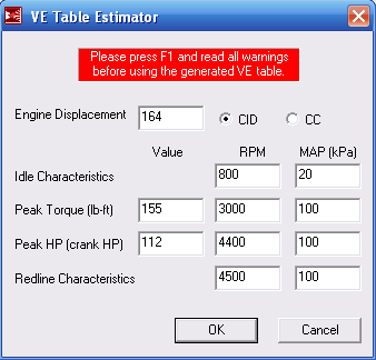
General:
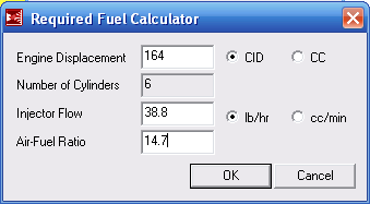
As you can see below, I stuck in 164 cubic inches which is the stock Covair displacement. However, with a 0.020" overbore the displacement is actually 166 cubic inches.
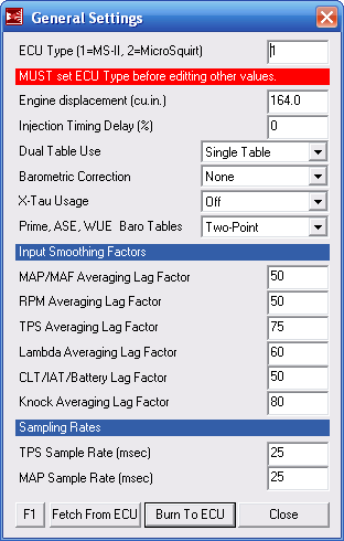
Idle Control: none
Spare Port Settings: all disabled
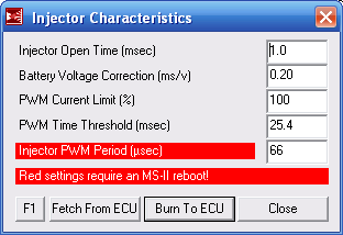
Injector Characteristics:
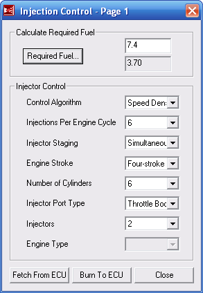
Injector Control:
The MegaSquirt online manual does not due justice how important these specific settings are. And although I've avoided rewriting their manual on my web page, I will go into a little more detail on this screen. Until I understood how all these settings affected each other, I was a bit lost.
The Required Fuel (shown here as 7.4) is how long in milliseconds a single injector serving a single cylinder should stay open for one intake stroke given 100% volumetric efficiency. In other words, this simply indicates how much fuel is required for one cylinder for one cycle based on the size of the cylinder and the flow rate of the injector. This number is the basis of which the VE table uses to generate a duty cycle. If the table's duty cycle states that 75% is needed for a given RPM and manifold pressure, the actual injector opening time is 75% of this Required Fuel.
The Required Fuel in the grayed out box (shown here as 3.7) is the value the computer actually uses for every crank rotation. So why should this be different from the first value of 7.4? For starters, I don't have one injector for each cylinder, on the throttle body I have two injectors for six cylinders. Also, since this is a four stroke engine, I only fill half of those cylinders each crank rotation. Additionally, as opposed to one big squirt for each crank rotation, I'm asking for three (which is six per cycle as shown on the screen). So...
- Two injectors doing the work of one changes Required Fuel from 7.4ms to 3.7ms ( 7.4 / 2 )
- Six cylinders as opposed to one changes Required Fuel 3.7ms to 22.2ms ( (7.4/2) * 6 )
- Only filling half of those cylinder every crank rotation changes 22.2ms to 11.1ms ( ((7.4/2)*6) / 2 )
- And breaking that one squirt down into three per rotation changes 11.1ms to 3.7ms ( (((7.4/2)*6)/2) / 3 )
A couple of things to note: I could have changed injections per cycle to a lower number and still may. The MegaSquirt manual has more information how higher and lower numbers come into play. The other real important factor is changing the Required Fuel base number to globally tune the engine. To give an example, if you are running lean, there are three ways to richen the mixture. (1) you could increase every number in the VE table, (2) you could increase the fuel regulator to a higher pressure, (3) you could increase the Required Fuel number.
I showed 7.4ms here, but with a 166 cubic inch engine (0.020" overbore) I get 7.5ms. To get the thing running the very first few times, I plugged in 10, 15, 20, and 25ms. At 25ms it was so rich it was blowing black smoke! So the plan is to find a Required Fuel setting and a fuel regulator pressure setting that work generally well, and then fine tune with the VE table.
And one other real important item... at 5000 rpm, one crankshaft rotation happens in 12ms. With these injectors opening 3.7ms three times per rotation, that totals 11.1ms. Now, the volumetric efficiency won't be 100% at 5000 rpm (and the resulting fractional duty cycle will open them less than 11.1ms), but that points out the fact that I can't simply take my 7.4ms setting and change it to 10ms, 15ms, or 20ms successfully. There simply would not be enough time at higher rpms to open the injectors as needed. If running lean and you can't increase the Required Fuel setting any higher, the only other options are to increase the fuel pressure or change the injectors to ones with a higher flow rating.
And this is the calculator that I used to get 7.4ms in the first place:
Rev Limiter: none
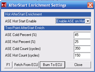
AfterStart Enrichment:
Accel Enrichment Config:

Other Fuel Settings:

2-Point Barometric Correction: not used
Flex Fuel: not used
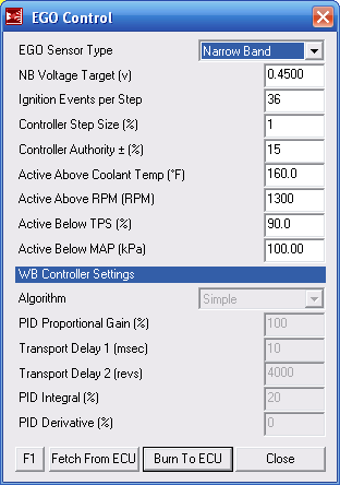
EGO Control:
The below settings control where the O2 sensors does its thing. I was initially concerned with the code's ability to provide closed loop operation for our application since we operate at 75% to 100% power; this is where a normal ECU would go into open loop and turn off O2 correction. However, you can see that I put the Active Below TPS at 90% (90% open throttle) and the Active Below MAP at 100kPa (100kPa is about atmospheric so unless you go turbocharged MAP will always be below this setting).
There was some discussion on the internet about running lean of peak during normal flight. One potential way to do that would be set the Narrow Band O2 voltage target from something other than 0.45 volts at a point where it runs lean (actually, normal operation of an O2 sensor is right on the rich edge of "economy" and you could just leave it there). The VE table would be set rich, the Automatic Mixture Control would be kept off (so the O2 correction doesn't change the VE table), and the Active Above RPM would be set higher than what I show (maybe 2200). When your throttle is open more than 90%, it runs open loop off of the rich VE table for "power". Pull the throttle back below 90% and it starts leaning per the O2 setting. Pull the throttle back some more (as in a descent) and it goes back to the rich open loop.
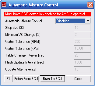
Automatic Mixture Control:
This was initially turned off, but will turn it back on with FLASH Update and with the disabled settings shown to allow the computer to adjust the VE table. I just didn't want the Stimulator to initially modify the settings.
Alpha-N Blending: not used
MAP vrs MAF usage: No MAF (mass airflow device)
IGNITION SET-UP
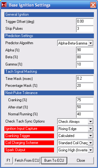
Base Ignition Settings:
It shows skip pulses to be 3, but I think I lowered that even more. This is how may initial pulses it skips before "sending calculated ignition signals" which either means it's not sending them at all or is sending them without advance corrections from the tables. I couldn't figure that out (and I didn't ask).
I'm using a Hall effect sensor that watches a hole in the flexplate. I've also wired my MegaSquirt so that this sensor grounds and completes the optical input circuit. So, when the Hall sensor is in front of the metal flexplate, the optical circuit is energized high. When a hole passes by, the circuit goes low. Which means, if I wanted to catch the front edge of my hole the Ignition Capture should probably be "Falling Edge". It runs now, but the ignition is probably 20 degrees retarded (which is the difference between the front edge and back edge of the hole). Just something I need to check.
Dwell Settings:
The 4.0ms dwell time is probably a little high. I think the spark is so strong with this setting that it's shorting through the spark plug wires where a couple of them touch metal. Now that I have it running, I'll lower this number until the spark is too weak to smooth run the engine and then turn it up a little from there.
At 5000 rpm, the crank rotates in 12ms and there are three sparks in that rotation. This means there is 4ms for coil to charge, discharge, and start again at that rpm. This consideration must be taken when setting Maximum Spark Duration.

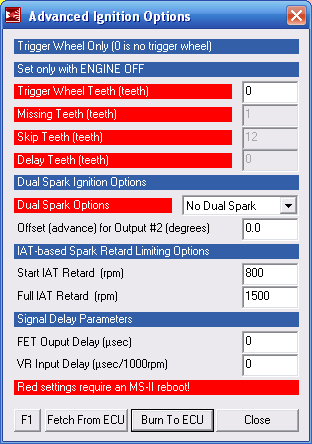
Advanced Ignition Options:
See that big-ol' zero in the Trigger Wheel Teeth setting? That shuts off all the missing tooth calculations. At one time that was set to 36 and I had a 36-1 wheel installed, but could not get that sucker to work. Now that I have a different starter and maybe after I get all the other settings tuned up, I'll try the 36-1 wheel again (I may consider a distributorless ignition system that would require it). But my three tooth wheel works just fine with the gutted distributor I have now.
Knock Threshold: not used
BASIC TABLES
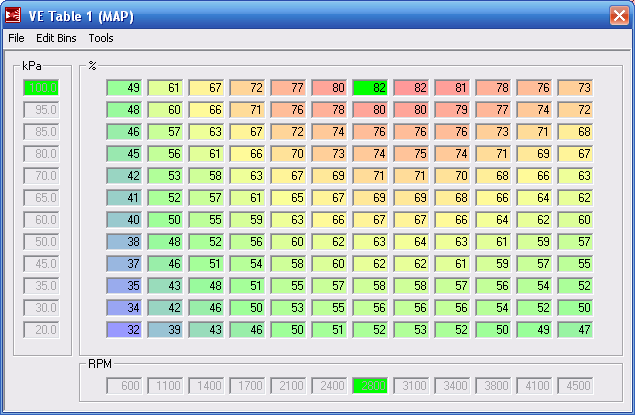
VE Table 1:
I used the Generate Table choice under Tools of the table window to initially fill my Volumetric Efficiency (VE) table.
This created the following table.
When I first got it running, the Required Fuel of 7.4ms was much too low, so I turned it up until the engine ran (almost doubled it at first). This could mean a few things. (1) my fuel regulator setting is way off, (2) my injectors are not 38.8 lbs/hr but actually lower, (3) or my engine gulps more air and has a higher HP and torque rating than I used in the VE Table Estimator.
I'm pretty sure the injectors and regulator are correct and those are easy enough to double check. The HP and torque numbers I got from the original GM data sheet on the stock engine. But since my engine doesn't have the same intake, the same exhaust, or a muffler it is likely that more air flows through this than the stock model. Consequently, it will have a higher HP and torque rating. Sweet.
ARF Table 1: not used
VE Table 2: not used
ARF Table 2: not used
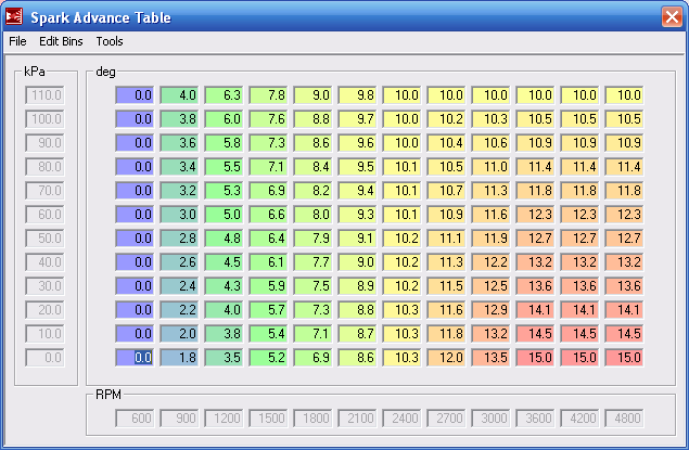
Spark Advance Table:
I studied the curves of several different EFI systems and found that they typically followed a pattern. At the lowest MAP (throttle closed, 0 kPa), the timing advances linearly to about 2/3 of the maximum RPM and then levels off. At the highest MAP (wide open throttle and a little ram air, 110 kPa), the timing advances a little quicker following a curve, reaches its max about 1/2 of the maximum RPM, but doesn't go as high as the lowest MAP values.
So using GRAPH PAPER, I replicated the two curves that I had been seeing (one curve for closed throttle and one for wide open throttle).
I started with 5 degrees at 600 RPM at both MAP values. At closed throttle I reached a maximum advance of 20 degrees at about 3600 RPM. At wide open throttle I reached a maximum of 15 degrees at about 2400 RPM. Using the nice curves drawn on the graph paper gave me smooth changes at all the incremental RPM settings. I just interpolated between the curves for values at all other MAP settings.
But when I initially tried to start it up, I had a couple of kickbacks. To make things a little safer, I simply selected the entire table with the mouse, a little math bar popped up, and I took 5 degrees out of the whole table. This put my low settings at TDC (zero degrees). When I want to add advance, I'll just select the whole table and multiply it by some number (like 1.5); this will keep the low settings at 0 and raise everything else 50%. Cool.
OTHER TABLES
Temperature Table Values:

The following tables are not used, which isn't to say that their function isn't being employed by a simpler single variable set somewhere else.
Alpha-N MAP Table: not used
Barometric Correction: not used
Priming Pulse: not used
Cranking Pulse: not used
ASE Percentage: not used
ASE Taper: not used
TUNING, X-TAU TUNING, OTHER TUNING
Most of the remaining tuning functions will require the engine to be completed and will help modify the VE and other tables and settings. However, there are a few worth checking into:
Warmup Enrichment in provided and is based on water temperature. In a Corvair engine there is no water. You either have to watch the case temperature, the oil temperature, or disable Warmup Enrichment. I will be using the oil temperature (the computer will think its the water temperature) and just left the enrichment settings at default. Obviously, water temperature and oil temperature will have different values for a "warm" and operating engine so I will have to adjust the setting when I get some experience on typical oil temperatures.
The Acceleration Enrichment for our engine MAY be different as well. In a car, you can put it in neutral and rev the engine very quickly. In an airplane, there will always be this large flywheel mass (the propeller) and the acceleration won't be as great. So either the enrichment will need to be set for a slower acceleration that the defaults, or it won't matter anyway.
Custom Electronic Fuel Injection (EFI) Engine Control Unit (ECU) for the Experimental Aircraft Corvair Engine
[Originally written in 2010]
The following page details the development of my Electronic Fuel Injection (EFI) Engine Control Unit (ECU) for my Experimental Aircraft Corvair Engine. This project was the result of my work getting my Corvair engine running with a MegaSquirt EFI ECU, with the goal of having an ECU tailored specifically to an experimental aircraft engine.
I'll admit, I'm not nearly the first person to develop an EFI ECU system; there are several from the DIY level to a fully developed professional package. But my goal here is to develop a system that is simple, reliable, and specific to aircraft engines. Aircraft engines are different than automobile engines in that they may start by hand propping, they run at near full throttle the majority of the time, and they don't require firmware subroutines that deal with transmissions, emissions, and a dozen other ancillary items.
The main comment I want to make is the importance of having a balanced design of the system. There are three areas of focus for an EFI ECU system: (1) The engine hardware, (2) the controller, and (3) the firmware. Several times I've seen where the builder spent a large amount of time working on the engine components (milling heads to develop port injection, working out really great looking fuel rails, custom intake manifolds) only to then just slap on a controller pulled from a car. The firmware running on the controller is equally, if not more important, than the hardware on the engine.
Custom Firmware, First Iteration
2010
Sometime while I was getting the Corvair running with a MegaSquirt controller, it became evident that I didn't have the level of control, nor the level of comfort, over the firmware running in the MegaSquirt. On their earlier revisions, they had made the source code available as "open source", but then they stopped on later revisions. I had the opportunity to review the source, and it was massive (it had every option for any engine incorporated). I wished to fix a bug and add some features and determined it would simple be easier to start from scratch.
The MegaSquirt is a nice breakout board for a Freescale microcontroller and has the necessary circuits for sensors, injector control, and ignition control. So I downloaded the free version of CodeWarrior from Freescale. After a few months, I had the basis for a future firmware.
This firmware was loaded onto the MegaSquirt module and bench tested, and appeared to operate as expected. In other words, this setup was not connected to an operating engine, but rather to an external simulator for the inputs, and the memory values were observed with a software debugger, and outputs checked by oscilloscope.
So at this point, I was confident that a complete firmware replacement for the MegaSquirt was within my ability.
Custom Controller, First Iteration
2010
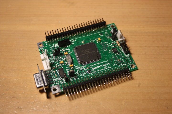
There were a few things I wanted to try with the controller and a few features I wanted to add (such as cylinder head and exhaust gas temperatures) and it was apparent that I was limited by the MegaSquirt controller. So I set out to start from scratch with a controller as well.
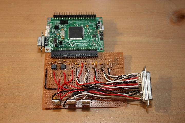
Since I had already written the code around a Freescale microcontroller, I researched Freescale prototyping boards and found the Adapt series from Technological Arts. Below is a picture of the Adapt9X12XS:
March 2013
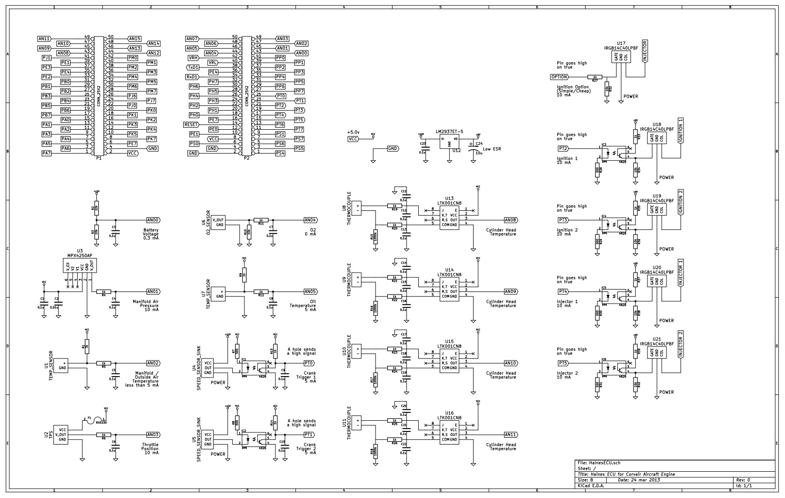
As a teaching aid, I reviewed the individual input and output circuits from several EFI boards. They all seem to be almost identical. But this made since they are all very basic circuits. Most inputs have a resistor to limit current flow, and a capacitor to filter noise. Some have a pull-up resistor, the voltage input is a voltage-divider, and everything else is based on a specific chips manufacturer's recommendations.
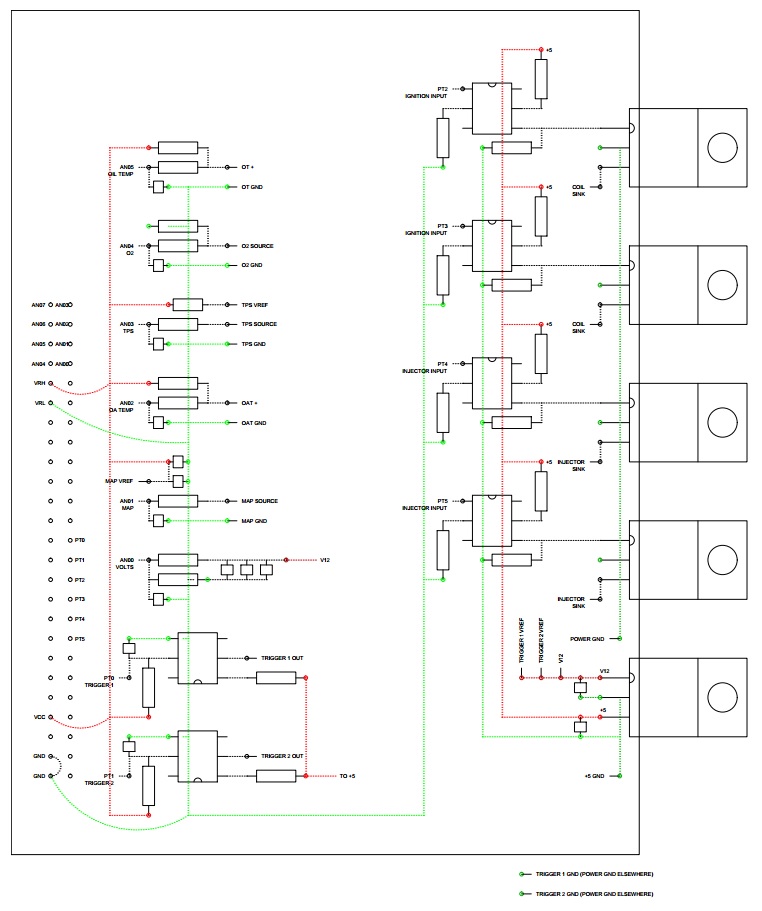
I was then able to layout the circuits I needed. The basic schematics are shown below:
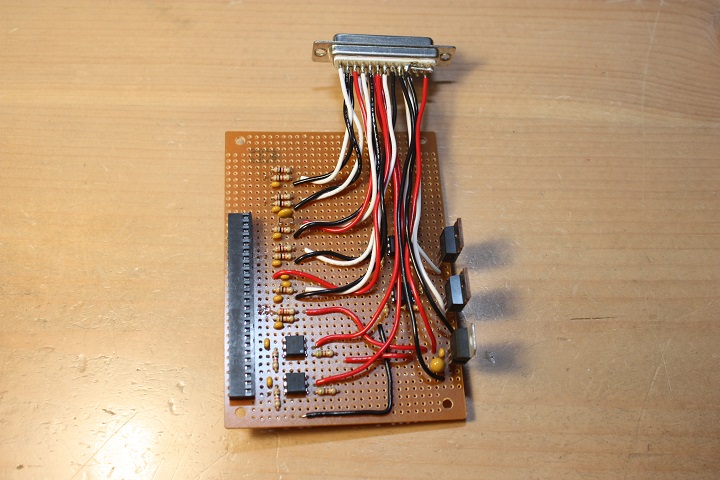
I also layed out the circuits on a prototyping board:
December 2013
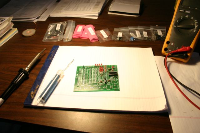
After two days of soldering, I had the prototype ready for testing. I only included one injector and one ignition circuit. With that exercise complete, I think next time I'll just order a printed circuit board.
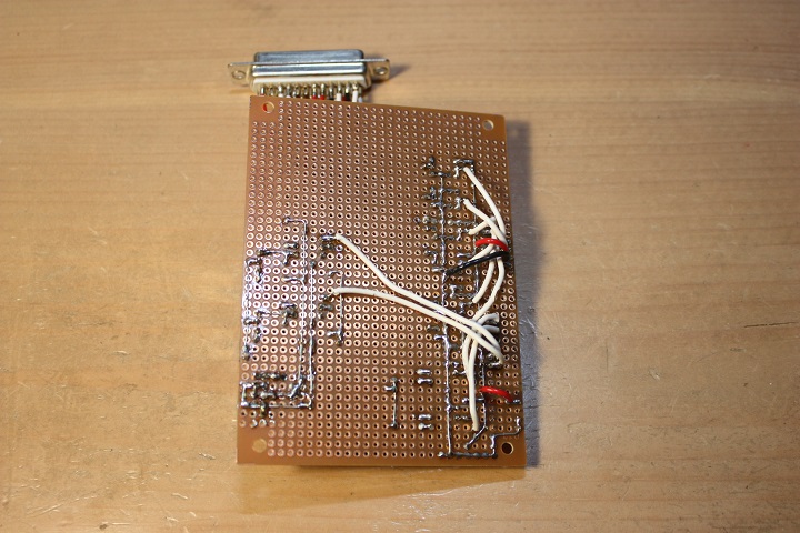
The proto board connects to the break out board:
Now, for future reference I have listed the details of the Harley throttle body I am using. In essence, the Harley throttle body is a port injection setup on the motorcycle since the output flanges bolt directly to the cylinder heads. I'm using it as a throttle body type system. And the main reason I'm using it is that in a single assembly, I have everything I need... a throttle plate, injectors, fuel connection, and all of the normal sensors.
One could surely do the same thing with any motorcycle throttle body, but this one was also readily available on Ebay.
Here are the specifics for the throttle body accessories. Since I would need to build connectors for everything, I've listed all of the connector details, all of which can be found at Mouser.com:
INJECTOR
Harley Davidson 27709-06A. 25 degree pattern type. 3.91 grams/s (31.03 lbs/hr) at 3.0 bar (43.5 psi).
Requires Delphi connector 15419715. GT 150. Push to seat.
- Terminal for 0.35-0.50mm2 (22-20 awg) Tin: 12191818
- Terminal for 0.35-0.50mm2 (22-20 awg) Tin: 15326264
- Terminal for 0.35-0.50mm2 (22-20 awg) Tin: 15396680
- Terminal for 0.35-0.50mm2 (22-20 awg) Silver: 13722266
- Terminal for 0.35-0.50mm2 (22-20 awg) Gold: 15326426
- Terminal for 0.75-1.00mm2 (20-18 awg) Tin: 12191819
- Terminal for 0.75-1.00mm2 (20-18 awg) Tin: 15326265
- Terminal for 0.75-1.00mm2 (20-18 awg) Tin: 15396679
- Terminal for 0.75-1.00mm2 (20-18 awg) Silver: 13722264
- Terminal for 0.75-1.00mm2 (20-18 awg) Gold: 15326427
- Terminal for 1.00-1.50mm2 (18-16 awg) Tin: 15396677
- Terminal for 1.00-1.50mm2 (18-16 awg) Tin: 15369261
- Seal for 1.2-1.9mm OD wires: 15366021
- Seal for 1.9-2.4mm OD wires: 15366060
MANIFOLD AIR PRESSURE (MAP) SENSOR
Harley Davidson 32316-99. Delphi 28004403. Pinout: A-Ground, B-Signal, C-Voltage (from left to right with locking tab down).
Requires Delphi connector 12129946. Metri-Pack 150. Push to seat.
- Terminal for 0.35-0.50mm2 (22-20 awg) Tin: 12084200
- Terminal for 0.35-0.50mm2 (22-20 awg) Silver: 12160222
- Terminal for 0.35-0.50mm2 (22-20 awg) Gold: 15326396
- Terminal for 0.50-1.00mm2 (20-18 awg) Tin: 15363934
- Terminal for 0.50-1.00mm2 (20-18 awg) Tin: 12048074
- Terminal for 0.50-1.00mm2 (20-18 awg) Silver: 12160223
- Terminal for 0.50-1.00mm2 (20-18 awg) Gold: 15366078
- Seal (several colors, several sizes): 15324982
MANIFOLD AIR TEMPERATURE (MAT) SENSOR
Harley Davidson 27381-06.
Requires Delphi connector 12162215. Metri-Pack 150.2. Pull to seat.
- Terminal for 0.35-0.50mm2 (22-20 awg) Tin: 12089290
- Terminal for 0.35-0.50mm2 (22-20 awg) Tin: 12124076
- Terminal for 0.35-0.50mm2 (22-20 awg) Gold: 12191054
- Terminal for 0.35-0.50mm2 (22-20 awg) Gold: 12191055
- Terminal for 0.80-1.00mm2 (20-18 awg) Tin: 12103881
- Terminal for 0.80-1.00mm2 (20-18 awg) Tin: 12124075
- Terminal for 0.80-1.00mm2 (20-18 awg) Tin: 12161184
- Terminal for 0.80-1.00mm2 (20-18 awg) Silver: 12162248
- Terminal for 0.80-1.00mm2 (20-18 awg) Gold: 12176860
- Terminal for 0.80-1.00mm2 (20-18 awg) Gold: 12191056
- Terminal for 0.80-1.00mm2 (20-18 awg) Tin: 15304790
- Wire seal included.
THROTTLE POSITION (TP) SENSOR
Harley Davidson 27659-06.
Requires Delphi connector 12065287. Metri-Pack 150.2. Pull to seat.
- Terminal for 0.35-0.50mm2 (22-20 awg) Tin: 12089290
- Terminal for 0.35-0.50mm2 (22-20 awg) Gold: 12191055
- Terminal for 0.50-1.00mm2 (20-18 awg) Tin: 12110236
- Terminal for 0.80-1.00mm2 (20-18 awg) Tin: 12103881
- Terminal for 0.80-1.00mm2 (20-18 awg) Silver: 12162248
- Terminal for 0.80-1.00mm2 (20-18 awg) Gold: 12191056
- Wire seal included.
IDLE AIR VALVE
Harley Davidson 27658-06
Requires Delphi connector 12162188. Metri-Pack 150.2. Pull to seat.
- Terminal list the same as the MAT Sensor
- Wire seal included.
OIL TEMPERATURE SENSOR
Common make
Requires Delphi connector 12162194. Metri-Pack 150.2. Pull to seat.
- Terminal list the same as the MAT Sensor
- Wire seal included.
January 2014
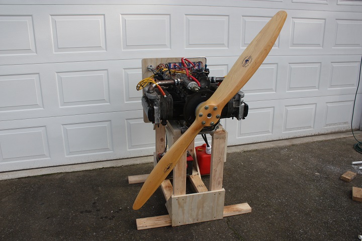
I had a nice test engine mount for my Corvair engine when I was in Illinois, and I even moved that stand to Oregon when we moved in 2010. But is was very large and in the way, and so I got rid of it and just stored the Corvair engine in the corner of my shed. Yep, I kind of which I kept it.
So I built a new one. It's simple, obviously made from plywood and 2x4's, and just a little embarrassing.
The Corvair engine and the Harley throttle body setup is exactly the same from my original MegaSquirt setup (read about this on its dedicated page). This setup is know to run and shall be used here for testing my new ECU and firmware.
Lesson About Grounding and a Good Battery
So I wired up my new controller and started testing the individual parts. I checked to see if it would connect to my laptop... good. I check to see if it read the sensors... good. I calibrated the sensors so that values were correct... good. I wrote a test program that would open and close the injectors a couple of times a second... good. I did the same thing with the ignition... good.
Then, I wrote a subroutine to fire the ignition several hundred times a second, just like you would expect at a high RPM... PROBLEMS! The spark on the plugs were good, but after a half a second or so, the spark would speed up out of control. Additionally, my injectors would randomly trigger at the same time. This would not happen if I slowed down the frequency of the spark, so I figured I was electrically saturating some circuit.
My first guess was that I was asking too much from the ground system of my prototype ECU. So I rewired it to relocate the EGBT (coil ignitor) off board with its own ground. These EGBT's are not cheap, and so I was a little aggravated when that one ran out of control and failed (it actually smoked with a little white cloud). I rewired grounds, added capacitors... I knew I was saturating the grounding system and it was screwing up the EGBT's of the coil and injectors, but I was at a loss.
In a fit of frustration, I removed my ECU and stuck the MegaSquirt module back on!
I guess I thought I would check the firmware on the MegaSquirt, and figure out my controller later. Now it came time to try to start the engine!
Deep breath, throw switch, "clunk" of the starter engaged, and it won't turn through a compression. Well, maybe my grounds are loose. I checked, found a few not tight, tightened, and tried again... still not working! OK, so maybe my shop battery is too small (but it worked several years ago). So I pulled the battery from my truck... still not working! So I jumpered the two batteries together... nope!
What it the world?! Two batteries and still not working?!! OK, put the truck battery on charge and come back later. Later, I flipped the starter, and THERE IT GOES!!! I didn't have the ECU on, I was just checking the starter, so it wasn't running... but at least it would turn over, and very quickly at this point! I took both batteries to AutoZone, had them checked, and both were bad!
With the new battery, I had no starter problem... and come to think of it, I probably wouldn't have had any ECU problems!
Lesson learned: Don't use old batteries.
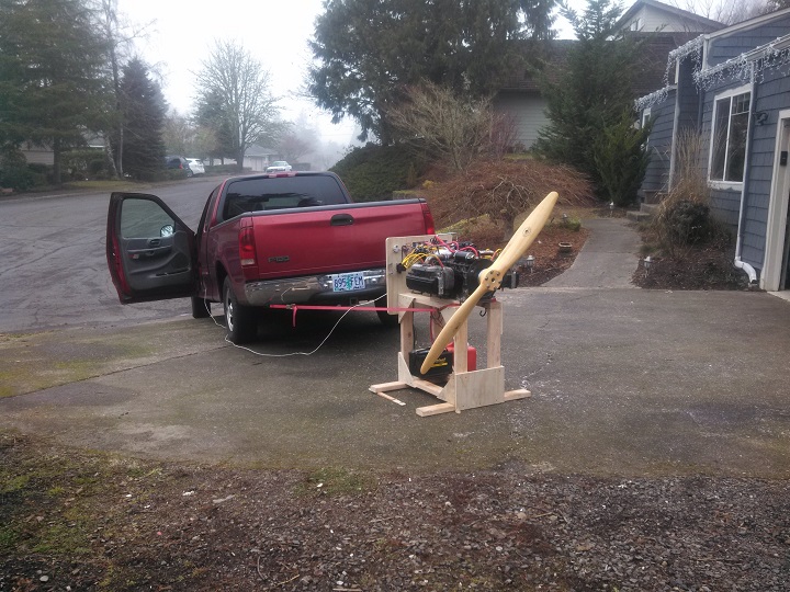
I strapped the stand to my truck. I plugged in the MegaSquirt module with my new firmware to my laptop to datalog the test. Once I had some initial fuel settings corrected, it ran!
Yep, my software works.
The Video of the First Run (MegaSquirt with Custom Firmware)
If you watch the video below, you'll notice that although it does run, it's running really rich and misses a few times. I stop it by turning off the fuel pump, and in that last second, it smooths out and picks up a bit of RPM. By choice, the top speed of that run was about 1500 RPM.
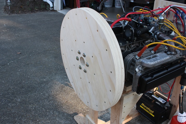
I did some other engine and software adjustments, and because I was working next to a spinning propellor, for safety I built a plywood flywheel.
Abandon MegaSquirt and Abandon the First Custom Controller
Now I was at a crossroads. I had a running Corvair on a MegaSquirt controller with my own software. What I ultimately want is a running VW (for my Thatcher) on my own controller with my own software. My plan is to use this Corvair on my "next" airplane build, and so if I have a custom ECU that works on either the Corvair or the VW, then my time isn't wasted.
I didn't see a need at this point to continue testing using the MegaSquirt controller or continue developing it's software. Basically, the MegaSquirt doesn't suit my needs, and so it comes off the stand and goes back into the drawer. What I have at this point is confirmation that my software will operate.
Speaking of software, the Integrated Development Environment (IDE) for the MegaSquirt and the Freescale breakout board that I had was a bit frustrating. The CodeWarrior IDE was fantastic, but it only ran on Windows, and I needed special hardware to upload firmware on my Freescale board.
It's been a few years since I made the decision to continue on with the Freescale controller, and in that time the Arduino breakout boards have become very popular. Because of their popularity, they are available everywhere (as opposed to my Freescale board which is available only from a single company located in Canada). Also, they come equipped with a USB port, a serial bootloader, and the IDE works on Windows, Mac, and Linux.
So I decided to port the project over to an Arduino Mega 2560. That work is shown in the following section...
Arduino based Electronic Fuel Injection (EFI) Engine Control Unit (ECU) for Experimental Aircraft
[Originally written in 2014]
The following page details the development of my Arduino based Electronic Fuel Injection (EFI) Engine Control Unit (ECU). This project was the result of my work getting my Corvair engine running with an EFI ECU, with the goal of having an ECU tailored specifically to a VW experimental aircraft engine.
Custom Controller, Second Iteration
February 2014
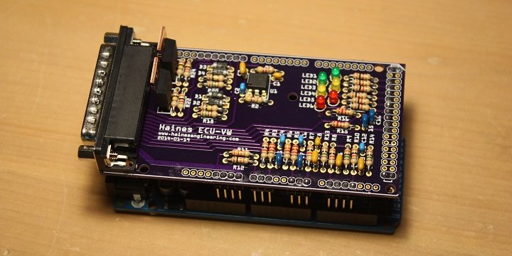
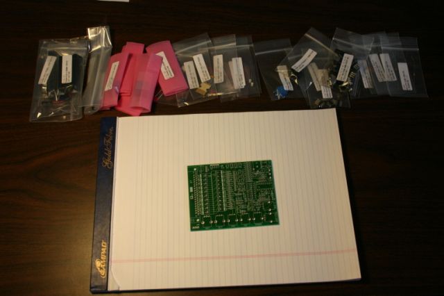
That soldering a "sea of holes" proto board like I did on the first iteration is just too much work. It was easier to develop a PCB and have a few prototypes fabricated. So after a weekend of board design, and a week waiting for the board to be built, I have a PCB:
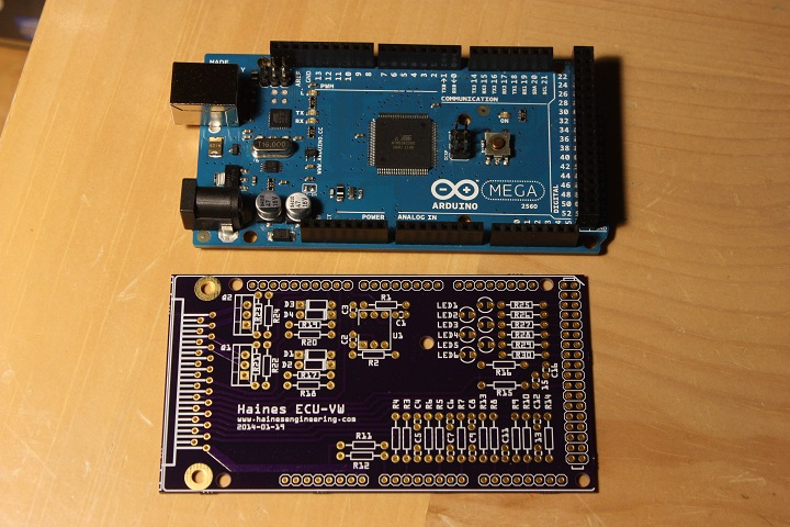
OK, this is cool. I have an Arduino Fuel Injection Engine Control Computer! Now I just have to solder components and convert the software for the new board.
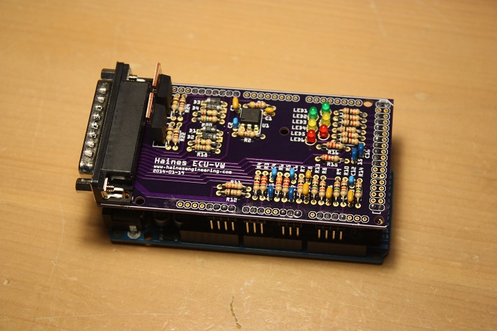
And a few days later I had the board populated and mounted to the Arduino:
Custom Firmware, Second Iteration
Arduino has a simplified IDE, and for the most part they have libraries available for typical microcontroller functions. This is great for learning, but I was about to develop a very complicated program, and I didn't want to get half way into it and find that their libraries limited me in some fashion. The price of simplicity is that lack of options. So I set up the Eclipse IDE to develop programs for the Atmel AVR Mega 2560 (which is the microcontroller on the Arduino board). In essence, I'm using the Arduino board only as a breakout board and do not plan on using any Arduino specific software.
After a few days, I had started from scratch, incorporated a few major changes to the way my ECU firmware is setup, and had rewritten my entire ECU code for an Atmel Mega 2560 microcontroller.
So without dumping all of the code on this web page (it is still under development) the firmware works like this:
-
The main loop has two subroutines:
-
The first reads all of the inputs pins and determines the corresponding value. For example, a ten bit A/D input will have a value of 0 to 1023, and that has to correspond to some formula that provides me the outside air temperature. So the first subroutine provides values for manifold air pressure, intake air temperature, oil temperature, throttle position, etc.
-
The second subroutine provides the calculated output. It looks up the volumetric efficiency and spark advance from two tables. It calculates the injector pulse width in microseconds (using the ideal gas law, air temperature, air pressure, the size of the cylinder, the desired air to fuel ratio, and the volumetric efficiency, and the injector flow rate). It calculates the advance time in microseconds. It calculates the coil dwell in microseconds.
-
-
So the main loop does nothing but go back and forth reading inputs and calculating outputs (about 1000 times a second). It is basically preparing for a future event.
-
Only when a crankshaft trigger is sensed does something actually happen. A interrupt service routine is called when a trigger is sensed, and that ISR then uses the previously calculated information to set a spark time and set an injector open time. But since this calculated information is ready and available, there is not a pause waiting for the math problems to be solved.
And that's pretty much it. OK, I've oversimplified and I've omitted explaining all of the error checking and safeties, but if the ECU doesn't have to worry about a dozen other car related stuff the basic fuel and spark control is fairly simple.
Connected to the Corvair
May 2014
So I still have my Corvair engine on its test stand and the Harley Davidson throttle body is still mounted (see my previous web pages), and so I've simply replaced the controller with the Arduino ECU:
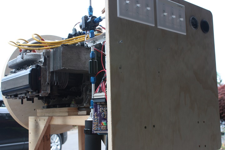
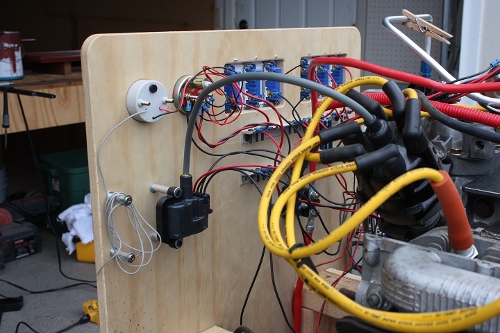
The other side of the test stand you can see the ignition coil from a General Motors LS1 engine. I'm using this coil since it has a internal ignitor and all I have to do is send it 5 volts. And if you really wanted to know, I'm controlling the injectors with the board mounted IGBT's (actually those IGBT's are ignition coil ignitors, so if they can handle an ignition coil they can handle a much smaller injector coil).
The Video of the First Run (Custom Controller and Custom Firmware)
May 24, 2014
If you watch the video below, you'll notice that although it does run, it's running really rich and misses a few times. It also has the timing retarded past top dead center... I really wanted to make sure that the ECU would spin the engine the correct direction before I did much else.
At this point, the controller was ready to be used on my next airplane.
[This turned out to be the Thatcher CX4 with a VW engine].
Trigger Wheel Experiments
The trigger on the current Corvair setup is a simple tooth located at top dead center for each cylinder. There are three crankshaft triggers for this six cylinder engine. The ECU has no idea which cylinder it is creating a spark for, this is taken care of by the distributor cap.
My future plan is to use coil packs, and so the ECU will have to be synchronized and know which cylinder it firing. Typically, this is done with missing tooth wheel or some other method to synchronized the ECU with TDC of cylinder #1. The downside is that the engine must spin about a full revolution before this can happen. This is great if you have a starter, but on an airplane I want to be able to hand prop if necessary.
When you hand prop an engine, you need to be able to start based on less than a 1/4 turn of the crank. So I need to have RPM and current cylinder information in 1/4 of a turn or less.
My solution is a set of teeth. For my VW, I plan on using three teeth for cylinder #1 and #3, and four teeth for #2 and #4. With three teeth, I can see the first tooth, calculate the RPM on the second tooth, verify RPM on the third, and trigger based on a missing fourth. Three teeth will indicate the #1/#3, and four will indicate the #2/#4 coil to be fired.
As a test, I built a crazy missing tooth wheel from a saw blade and mounted a test rig with a hall effect sensor. I wrote up a routine to count teeth, perform calculations, and indicate spark. This was successful.
Additionally, I wrote a subroutine to spark only above a certain RPM. If one is hand propping an engine, you don't want an accidental spark if you move the propeller in position (I'm sure to also have a switch on the panel to set "switch off" or "contact" as you would normally expect in an airplane). So, now I have the routines I need to gather RPM and current cylinder in less than 1/4 turn.
I could find no other wheel that used this exact type of encoding. So, if I get this working, and in several years we find this method being used on other engines, I just want to say that it was my idea (insert smiley face here).