Facetmobile Construction
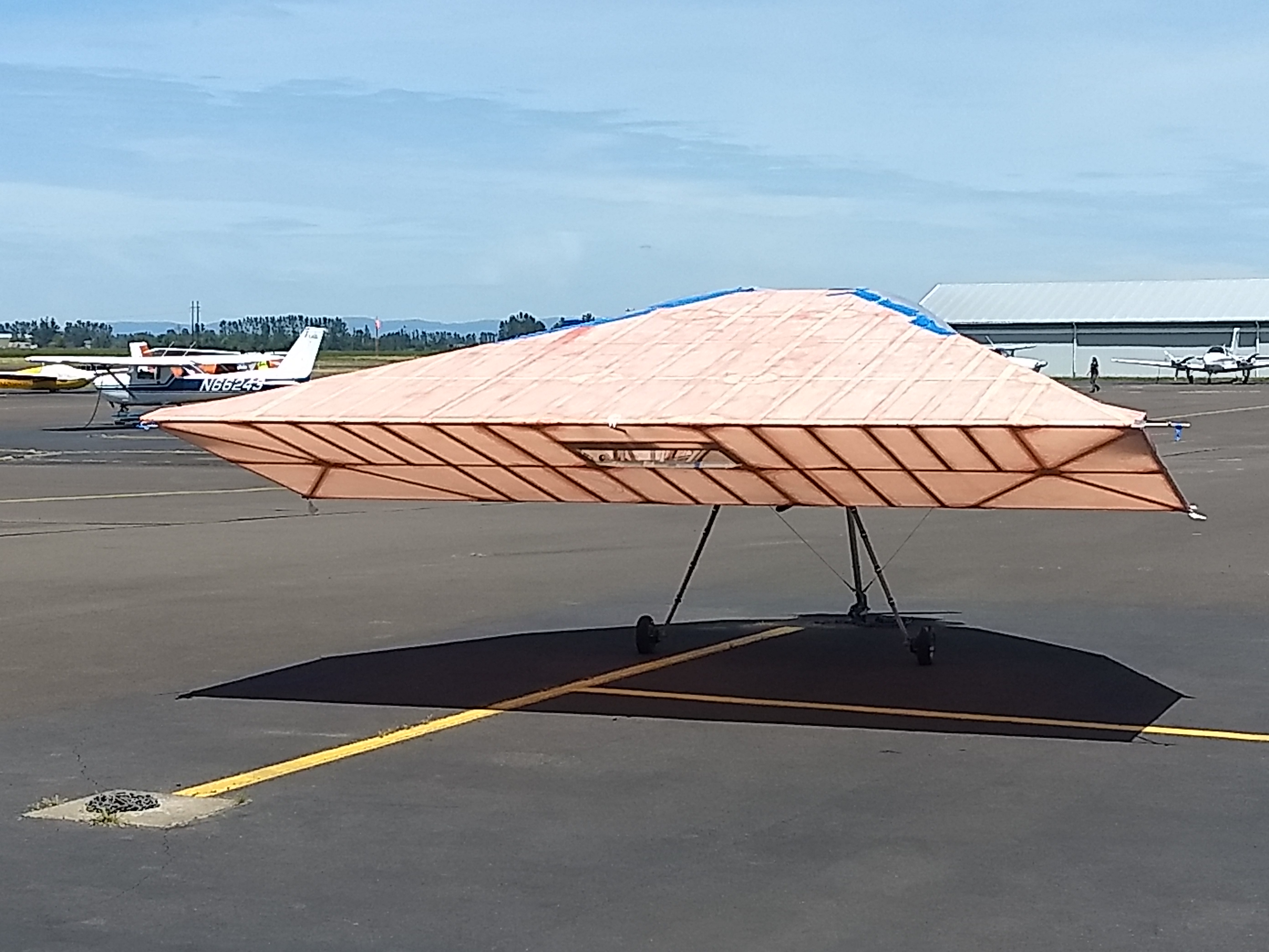
The original FMX-4 Facetmobile was designed and built by Barnaby Wainfan, Rick Dean, and Lynn Wainfan back in 1993 and made quite an appearance at Oshkosh in 1994. It is a lifting body aircraft; in other words it has no wings, the fuselage provides the lift.
Several years later a second FMX-4 Facetmobile was built by a group from the Experimental Aircraft Association (EAA) Chapter 292 located in Independence, Oregon. This page summarizes that build, and the custom software and CNC router used to fabricate the aluminum tube structure. This page also summarizes the initial construction of the FMX-7 Facetmobile, the two place version developed and built by Barnaby Wainfan.
I want to make this very clear: This page is not about the aerodynamic designs, flight characteristics, construction plans, or build kits for the Facetmobiles. This page only details the specialized software and CNC tools developed and used to help build the structure of those aircraft.
Barnaby is a friend of mine, and I have agreed not to supply any of the designs, geometry, or CNC cutting files. Please do not ask.
If you have additional interest in his work, please follow the following links:
Barnaby's website: https://wainfan.co
Barnaby's newsletter: https://barnabywainfan.substack.com
Barnaby's channel: https://www.youtube.com/@bw8039
What I find coincidental: I have been to Oshkosh only twice. The second time was in 1994, and I saw the Facetmobile on display. It was the only one and the only year that it was there. Hard to miss, it was at the entrance. Two decades later and I am working on a Facetmobile project. Small World.
FMX-4 Facetmobile Construction
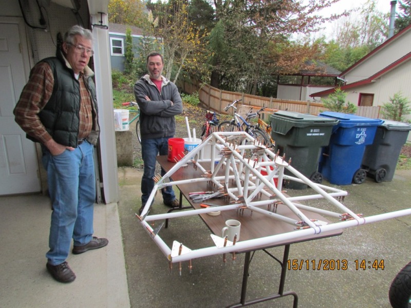
In 2013, enter a group of active builders from EAA 292. This group decided to revist the design, with Wainfan's knowledge but not participation, and build one. The goal of the effort was not to redesign the aircraft, but refine its construction details... and then of course end up with a flying aircraft! This initial group included Robert "Bob" Ingle, Ernie Moreno, Vince Homer, Denny Fuhrman, Bill Hoffman, Curt Anderson, Bill Higdon, and me, Robert Haines.
Preliminary Work
November 2013
The basic structure of the aircraft is aluminum tubes connected with riveted gussets. The Wainfan prototype was hand cut and built, and because so, the exactness of how the tubes fit together was subject to hand cutting and grinding. Many of the connection points have multiple tubes clustered and nested, and almost none of the angles are simple right angles. In other words, this design is not one that can be built easily by hand and is very difficult to get all of those tube connections accurate.
And this is where I got involved. The goal was to develop a method that would allow the tubes and gussets to be pre-drilled and cut with profiles that would allow them to fit together precisely.
"Pre-Drilling" is a construction technique where parts are pre-drilled with accurately located rivet holes, which should perfectly line up when the parts are properly positioned. The alternative is "match-drilling", where the parts are positioned first and then rivet holes are drilled through both pieces. The benefit of pre-drilling is that is speeds up assembly, and holes only line up when you have the correct parts in the correct position.
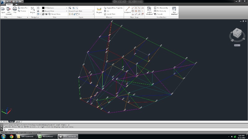
The first step was to layout the fuselage in a 3D CAD model. In this fashion, the layout could be reviewed by the group, and then tube lengths and angles could be acquired from this model. Bob Ingle and Ernie Moreno visited Barnaby in California and took field measurement of the original prototype. Bob developed the initial CAD model from this data.
Software
The next big step was to develop the software to create the CNC cutting files. The initial data need to include:
- A list of the joints/nodes and their 3D positions.
- A list of the tube sections using these nodes. This included the starting node, ending node, diameter, and wall thickness of each section.
- Details of the hierarchy of each section. This information either connected sections into continuous tubes, or defined which tube notches into which other tube.
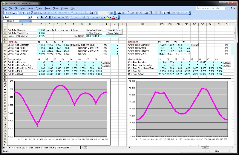
Microsoft Excel / LibreOffice Calc was used to record the above information. The integrated Visual Basic was used for the calculations. This was a somewhat atypical path to create "software", but it was quick and provided an immediate user interface. My goal was not to publish a piece of software. I just needed a quick and dirty tool.
- The angles and rotations between the sections were determined using the dot product and cross product (remember Vector Algebra?).
- Using the included angle, the diameter of the uncut tube, the diameter and wall thickness of the cut tube, the coping path was developed.
This calculation uses a common formula for tube coping, and it provides a position where the tube surfaces intersect for any given position of rotation. There are many tube coping calculators on the internet, and a few sites post this math. I used this basic formula to list the offset for each of the 360 degrees of rotation. Then:
- Calculate for both the inside and ouside diameters of the cut tube.
- Repeat for every other uncut tube at that junction.
- Combine and use the deepest cuts at each degree.
- Add additional clearance for the a cutter diameter offset.
- Using this data, create a GCode cutting text file
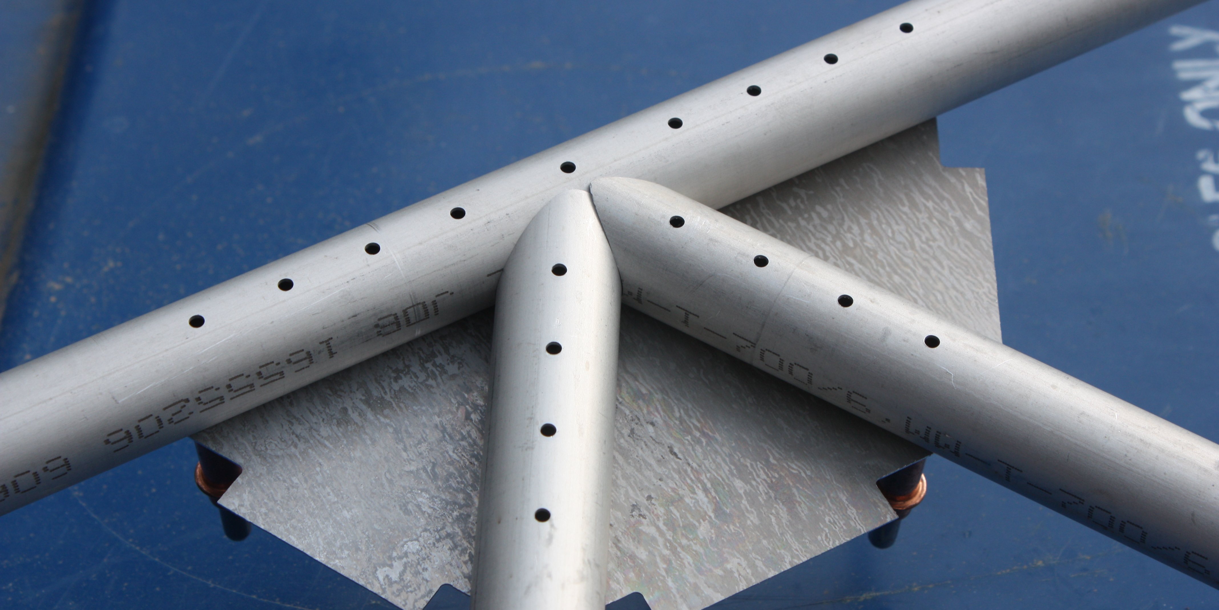
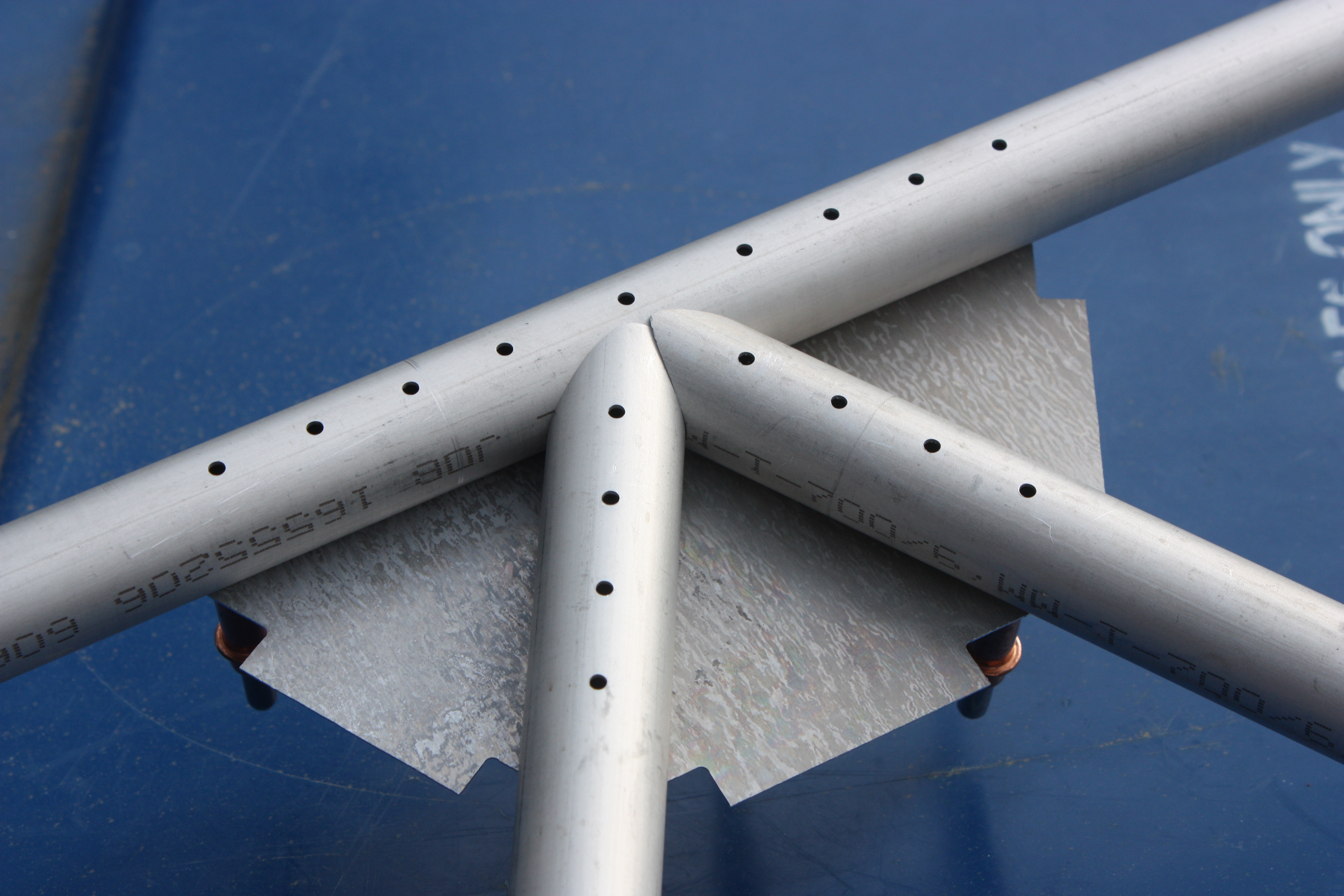
Barnaby is adamantly against welding the 6061-T6 aluminum tubes on this project. I asked, he's not having it! So each group of tubes are held together with riveted gussets. The gussets information needed to include:
- Which tubes and on which side the gusset is located.
- How many rivets per tube.
- If this gusset piece is part of a larger gusset connecting multiple tubes.
- The position of the resulting holes on each tube.
After days of software development (weeks actually) the tube cutting files, with exact coping on each end and rivet holes included, and the gusset cutting files are created automatically.
This screenshot shows the calculated coping paths.
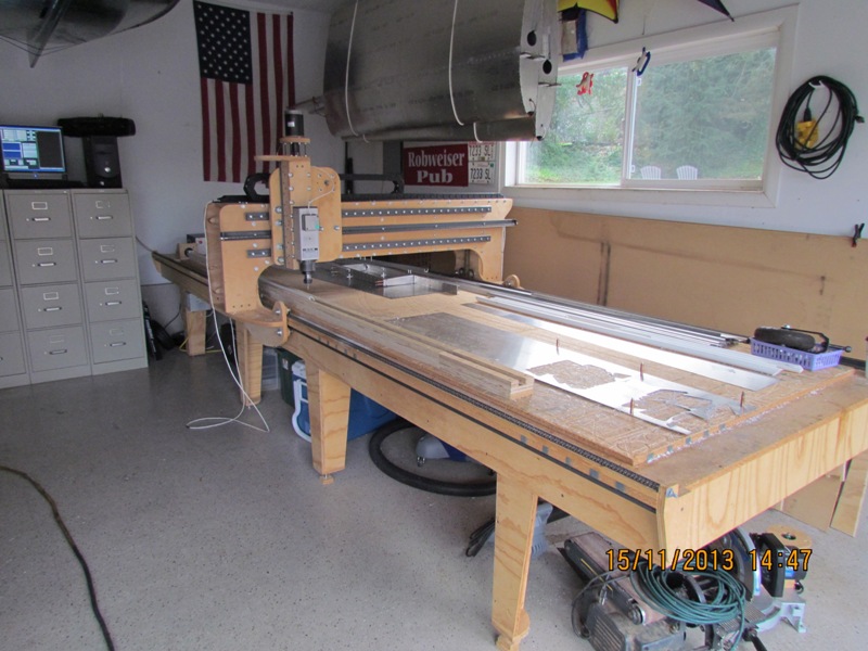
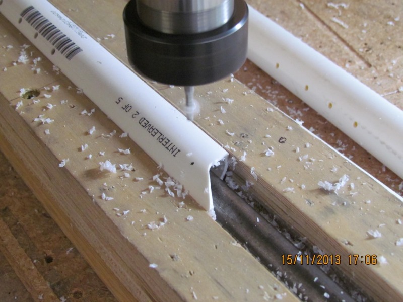
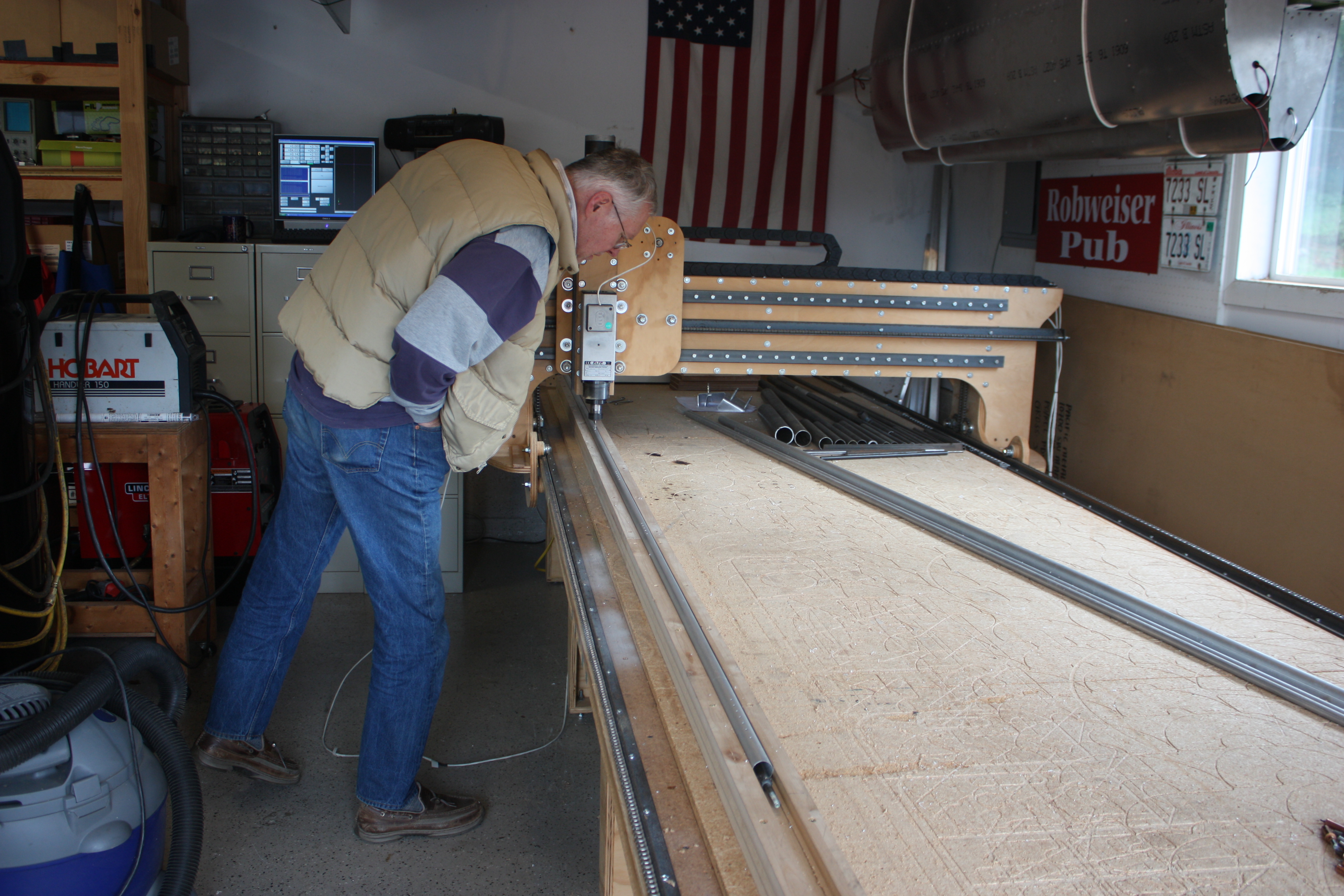
CNC Setups
My Worktable CNC was set up with a fourth axis used for rotating the tube. The tube rotated in in a long precision wooden trough, and the X, Y, and Z axes were positioned as necessary to make the coping cuts. You can see this fixture along the left side of the CNC table:
PVC water service pipe was used to develop the process and create a scale model. The PVC cut nicely, cut quickly, and was the same diameter as the aluminum tube:
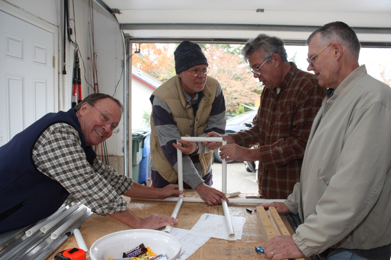
1/3 Scale Prototype
The next phase of work was to build a 1/3 scale model of the Facetmobile but with full size tube diameters. It was noted that even at scale, the angles, notches, and gussets would be the same as the full sized prototype:
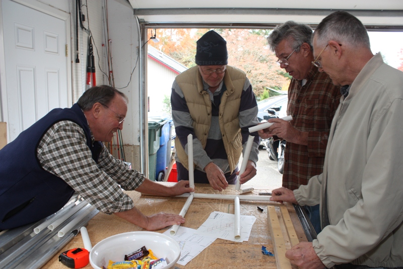
The builders are Denny, Bob, Ernie, and Vince. I (Robert) am behind the camera so I am never in any pictures. :)
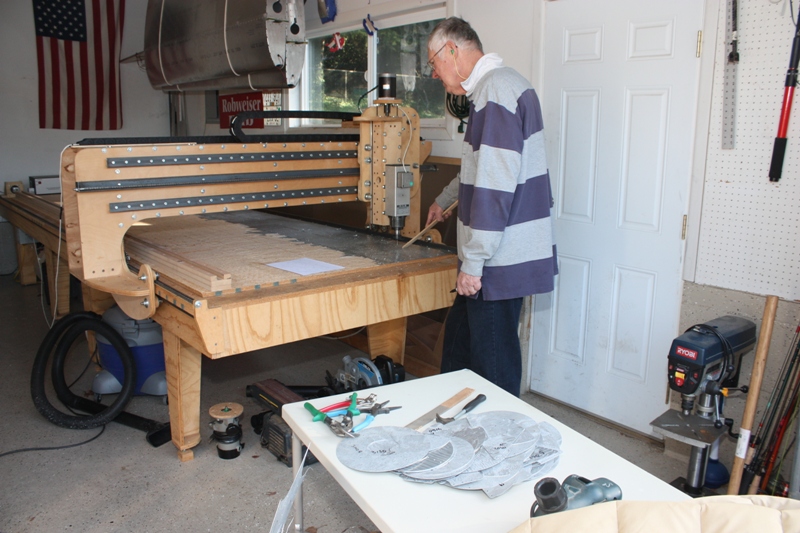
Bob running the CNC. The stick is to hold the thin aluminum without risking a finger. After a few gussets were cut from scrap aluminum, the model simply snapped together:
After a week or so, we had the major tubes included in the model:
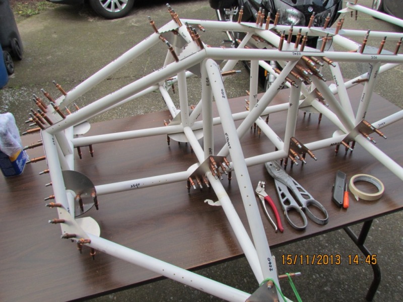
Just to get to this point, every tube had to be cut two or three times due to changes or corrections. Coordination of the details was a massive undertaking, and this initial work helped us get methods in place to allow us to move on to the next more complex step.
Full Size Prototype
January 2014
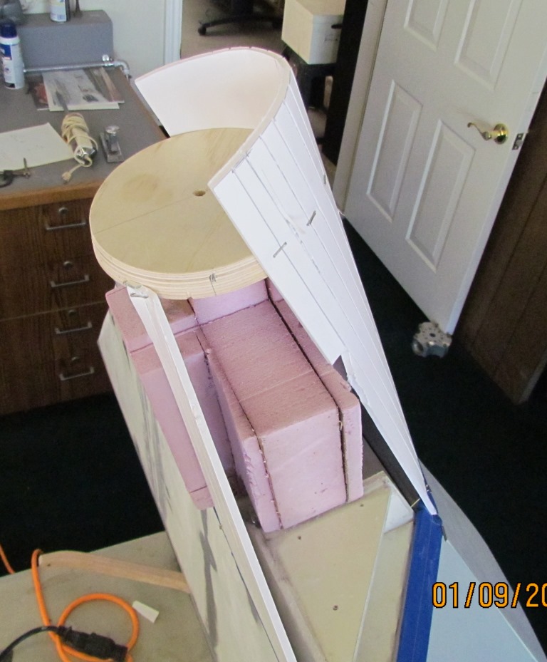
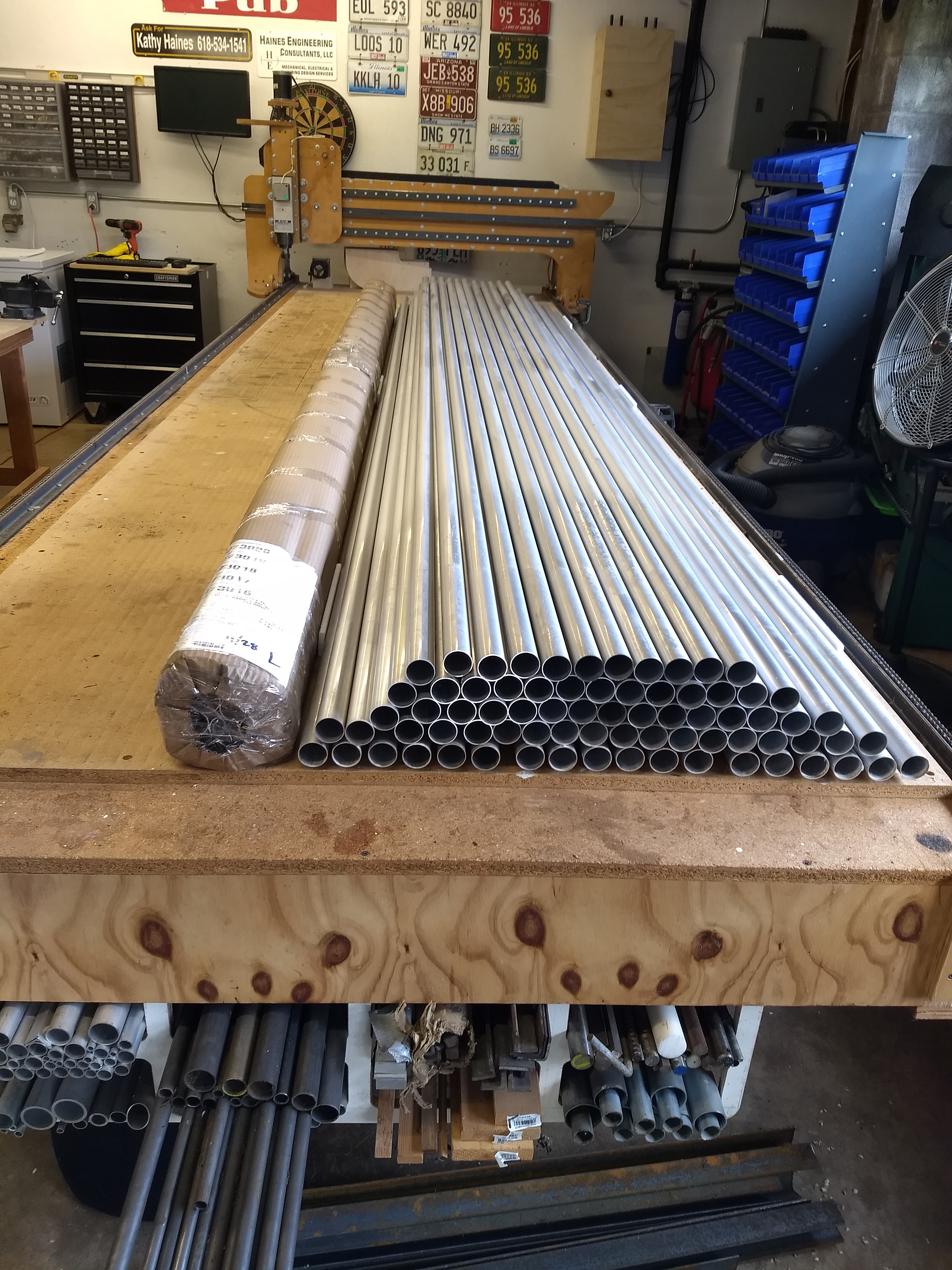
The original plan was to go directly from 1/3 scale PVC to full scale aluminum first prototype. Knowing that we would likely waste a lot of tube developing the prototype, it was decided to build a full size PVC model. Aluminum tube is expensive!
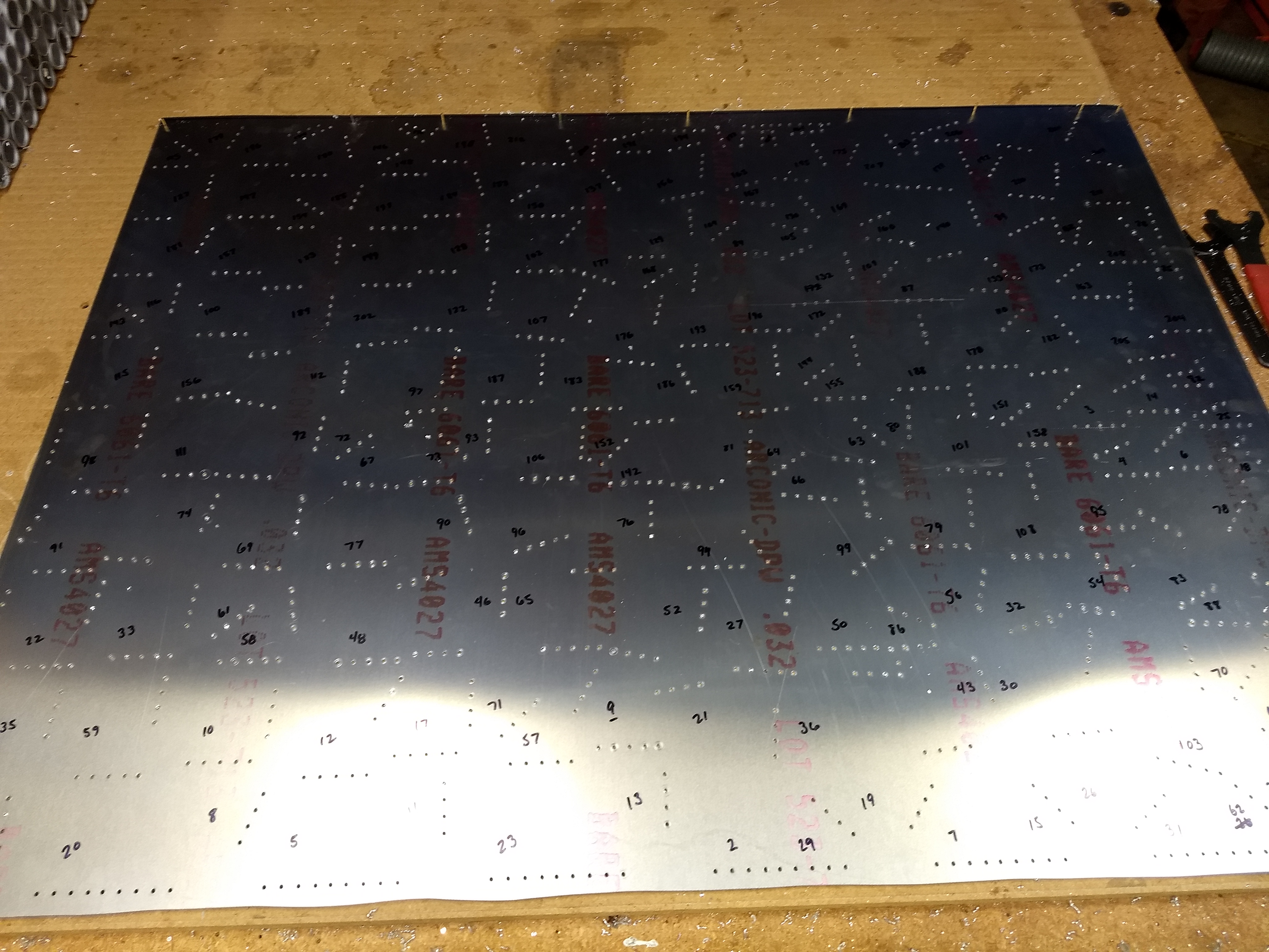
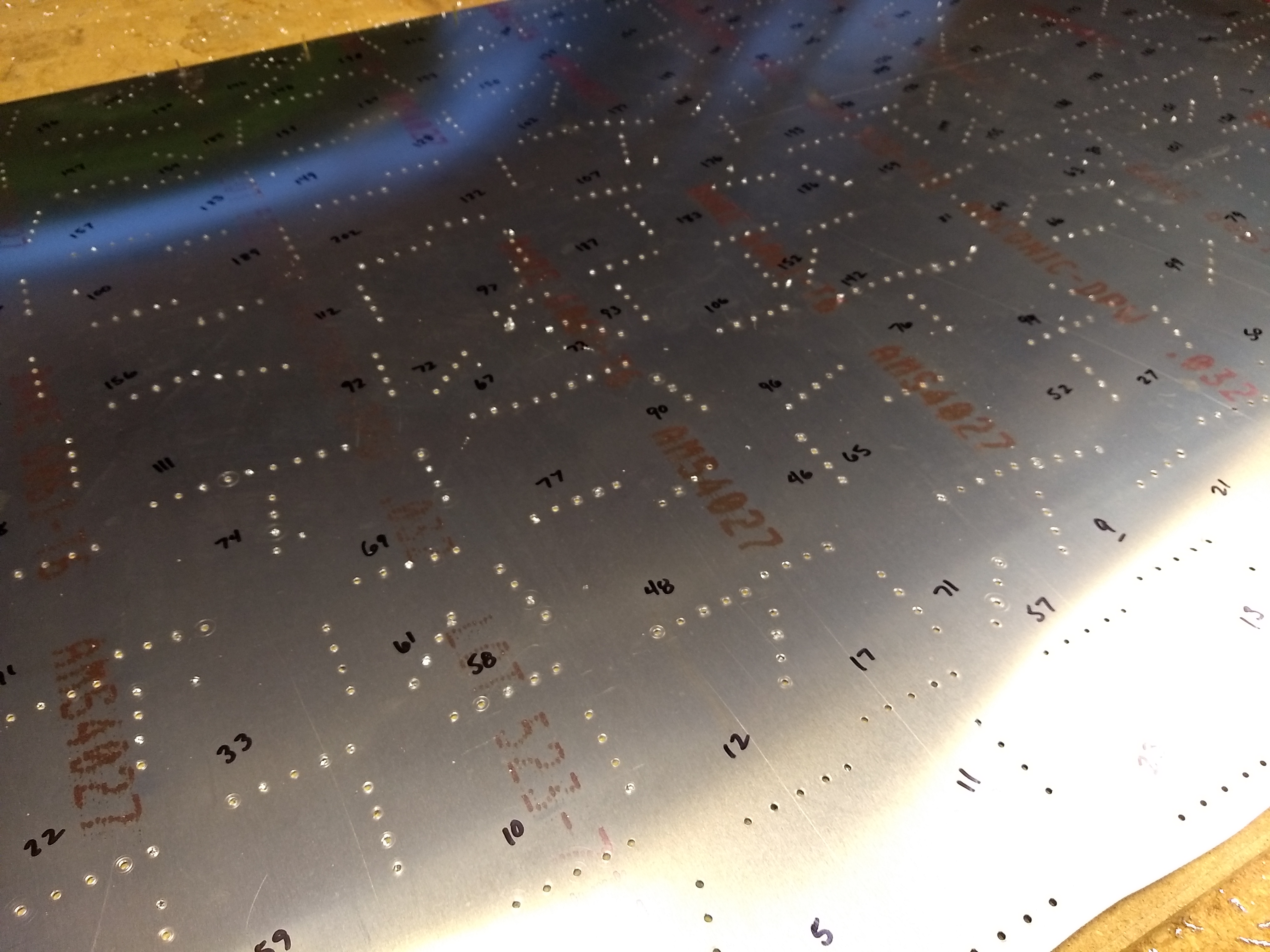
Cutting Aluminum Tubes and Gussets
March 2014
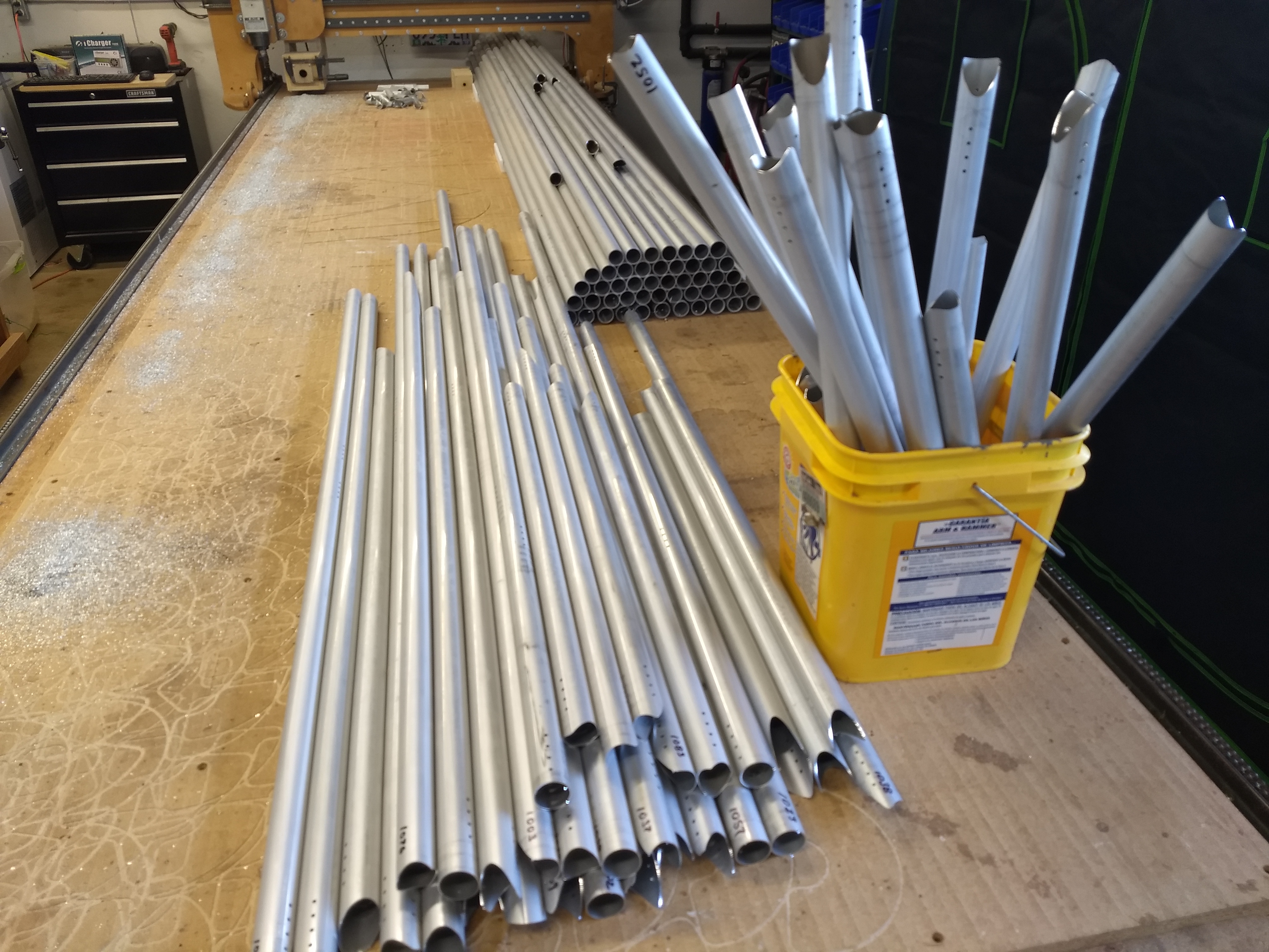
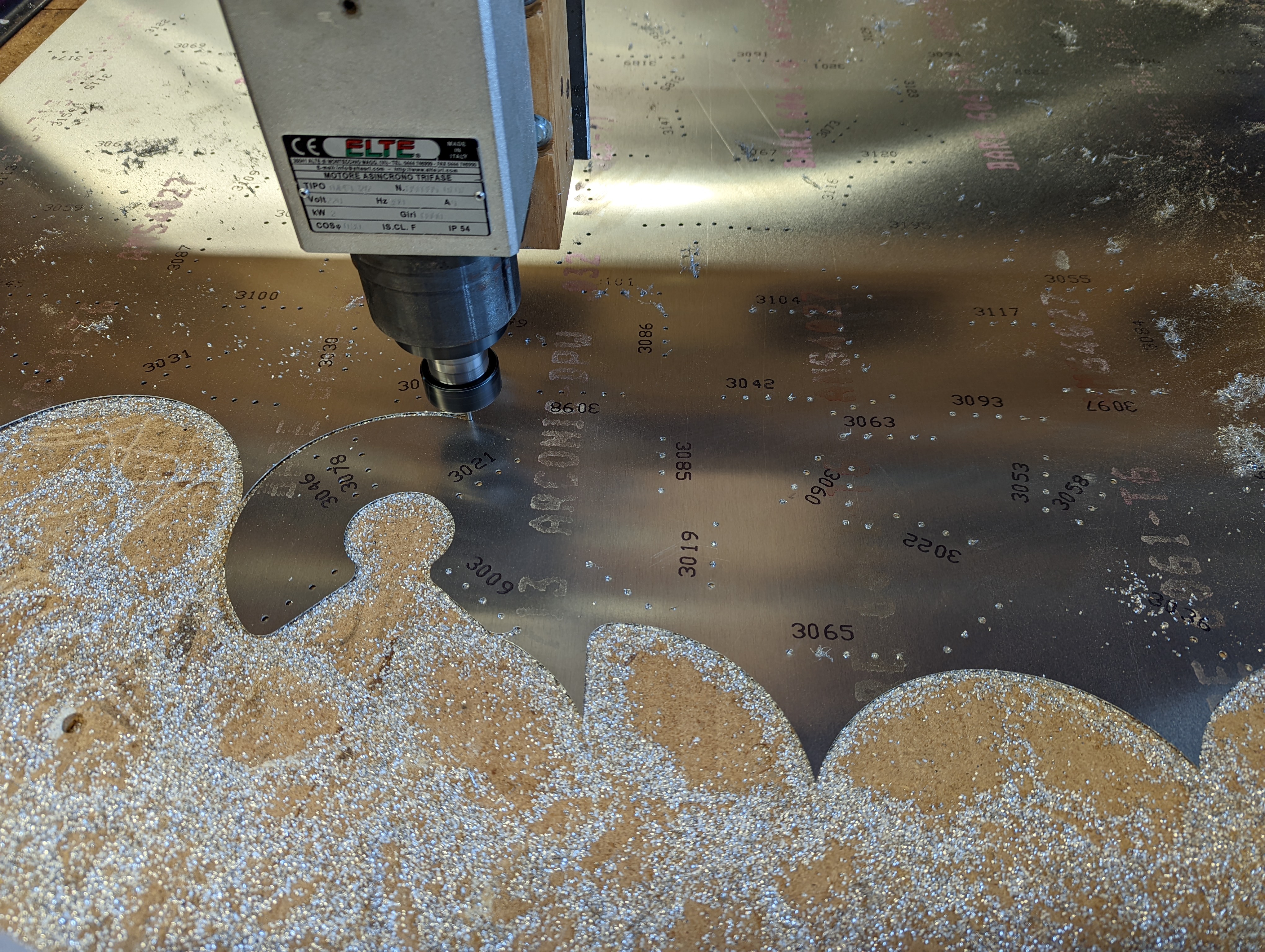
To cut aluminum tubes and thin sheet on a CNC router, you need a down-cut "o-flute" bit. This is a special router bit that has a continuous curve flute. This keeps those sticky hot aluminum chips from packing up in the bit. (If you want to see that happen, try cutting using a standard square fluted router bit.)
Bob running the CNC:
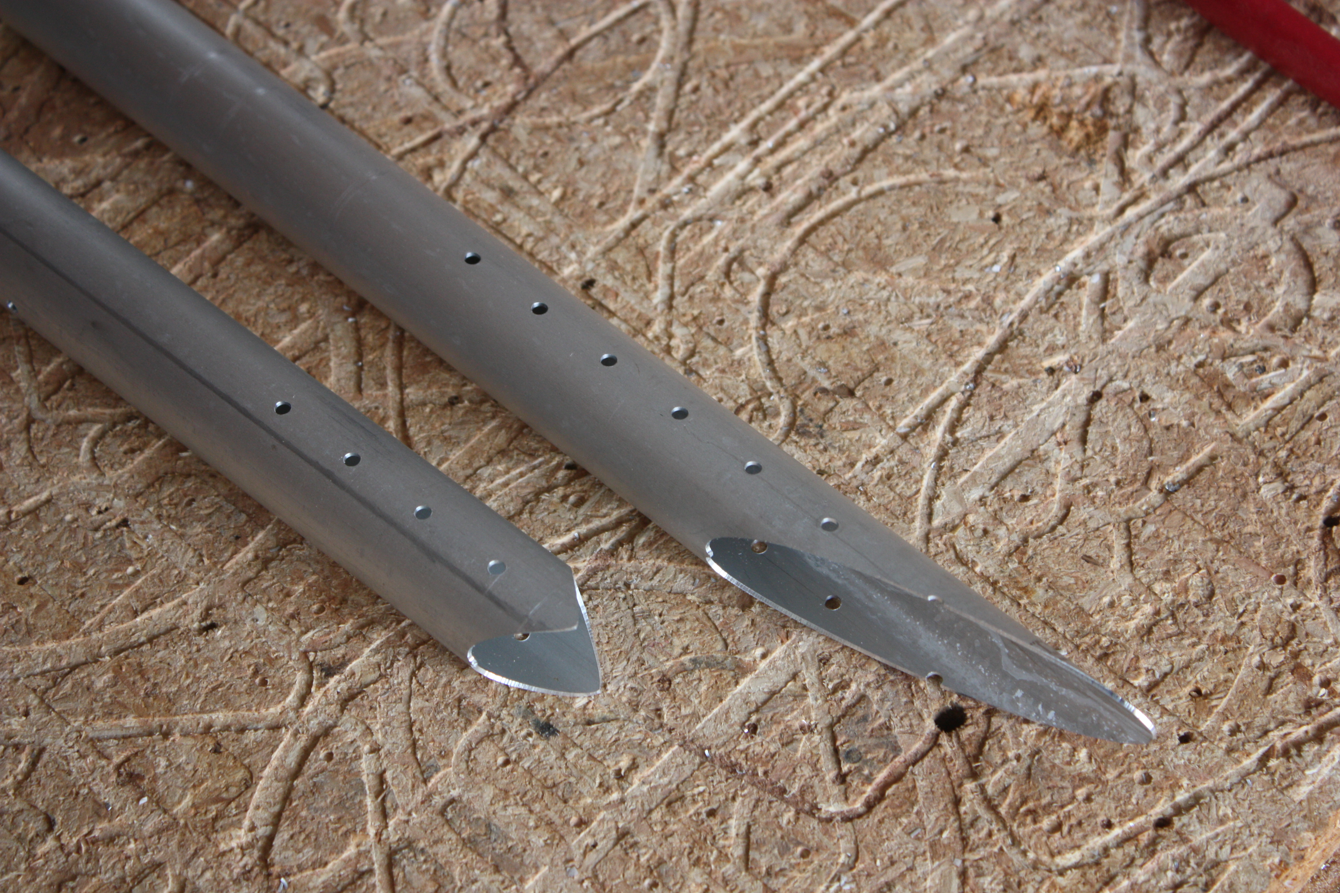
You can tell the tube on the left will fit onto another at a right angle; the end cut is small and even on both sides. The tube on the right fits onto another at a very shallow angle; the end cut is very deep on one side:
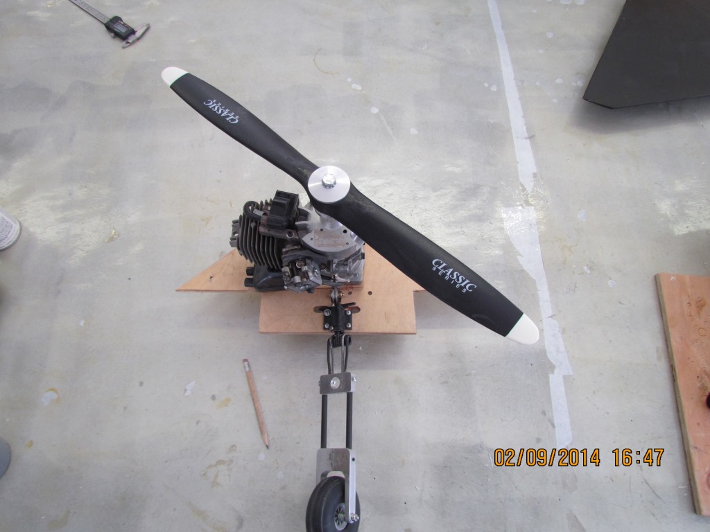
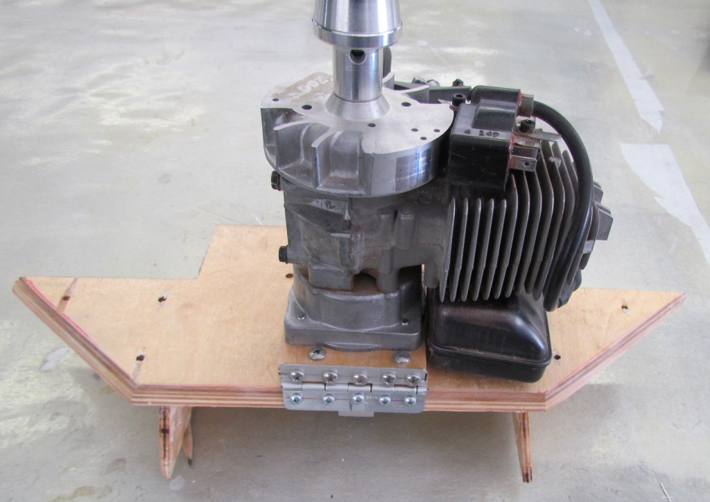
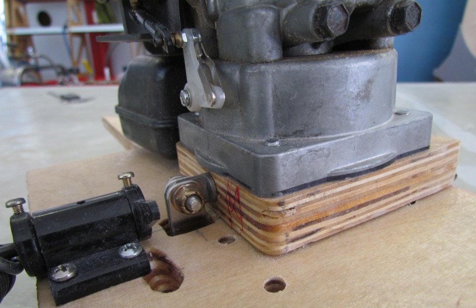
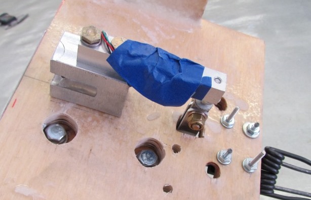
Radio Controlled Model
September 2014
While waiting on me to cut a batch of tubes and gussets, Vince decided to make a RC model of the Facetmobile!
Fuselage:
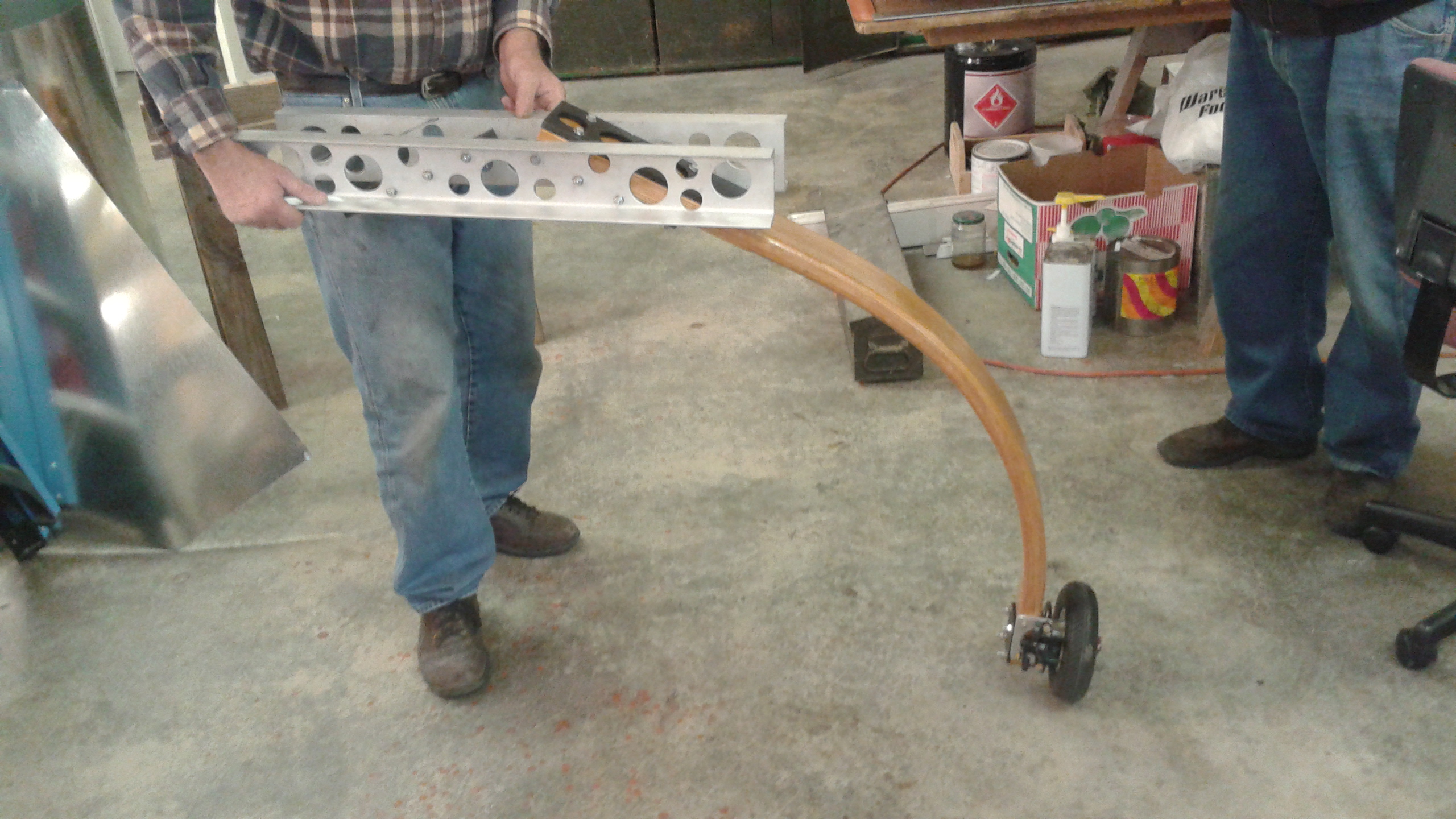
Landing Gear:
Engine:
Finished:
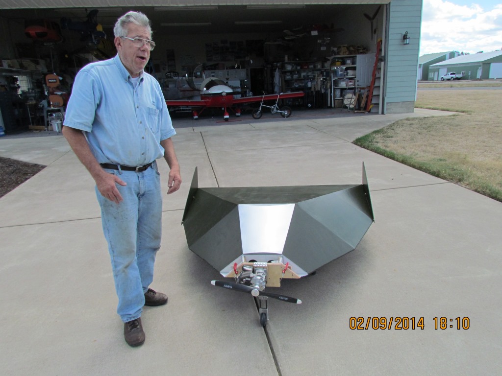
Vince and Ernie:
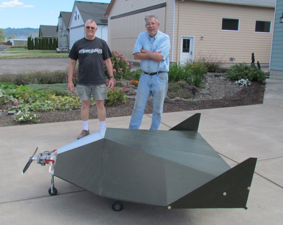
Actually, two were built. A nitro-powered version and a smaller electric:
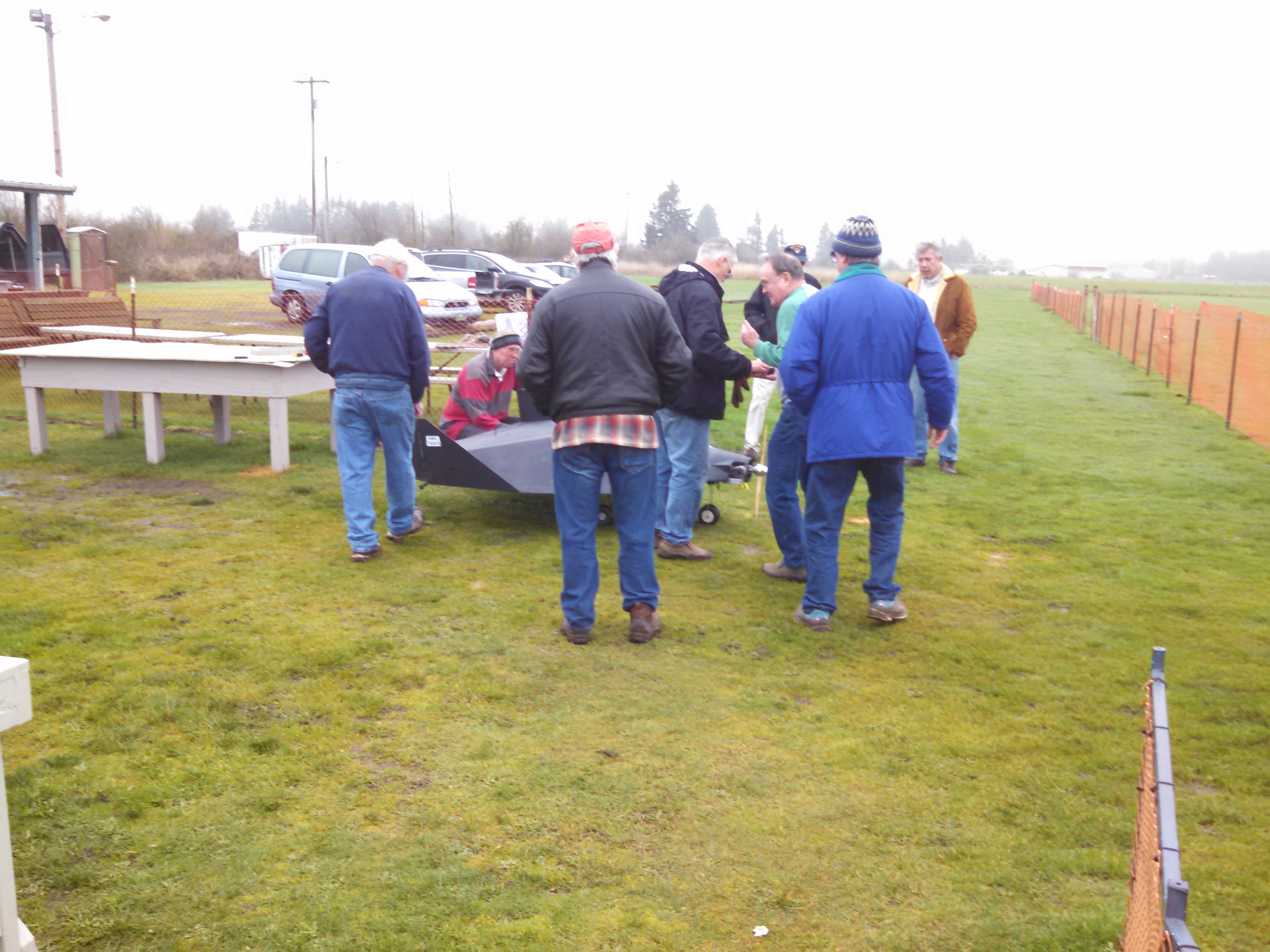
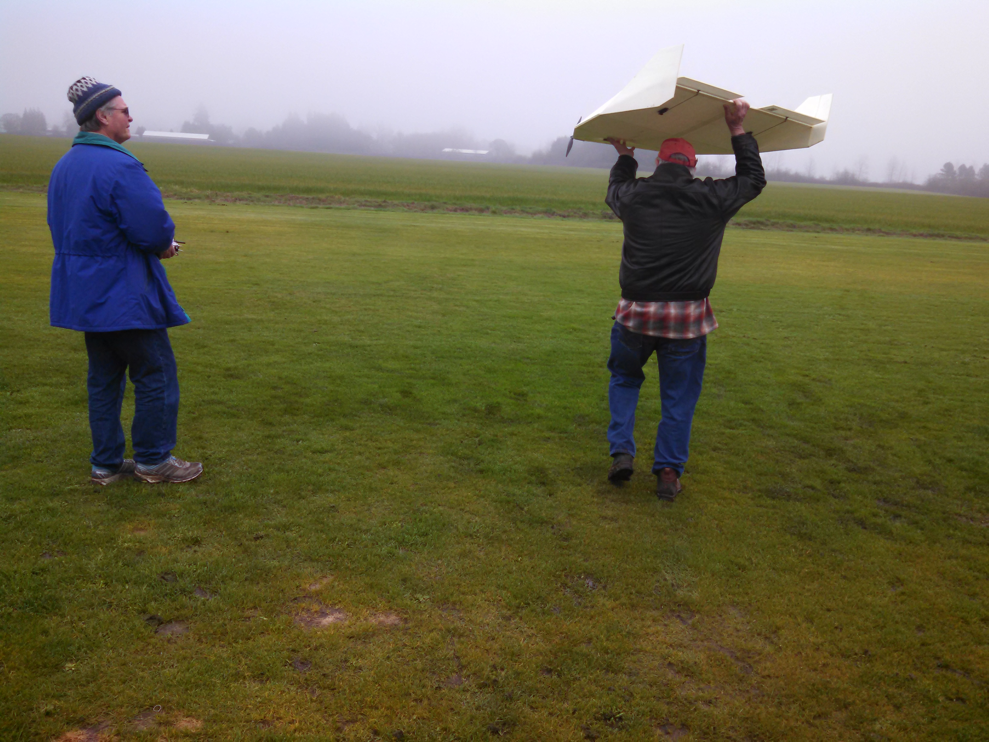
On the test flight day, the field was wet and muddy and the nitro-powered was not developing adequate thrust. The only one that flew that day was the hand-launched electric.
It actually flew well... as expected.
And a bit of video of the RC Facetmobile:
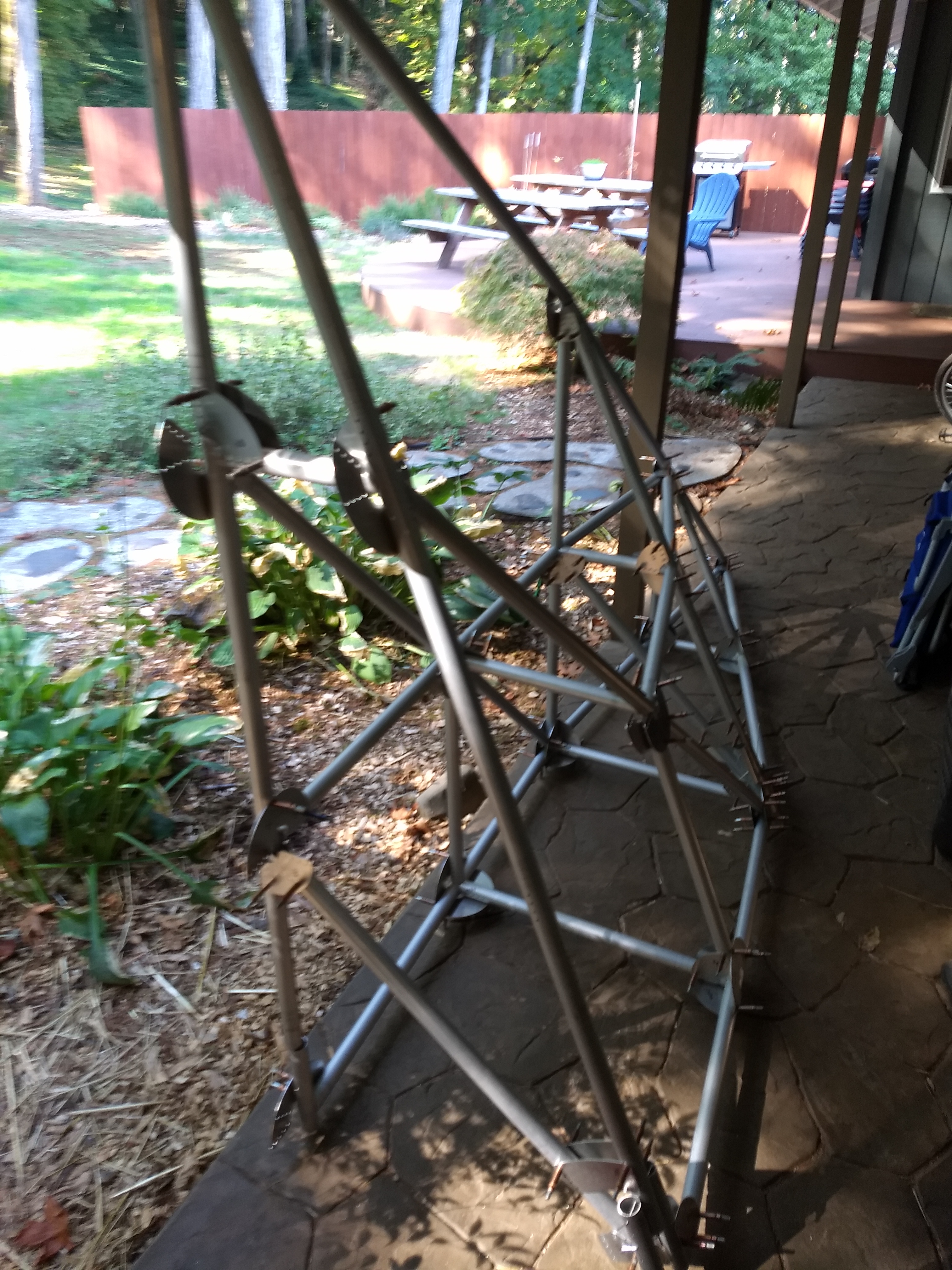
Tube Assembly
September 2014
The first batch of tubes were ready to go. Once they started, it was assembled with Clecos pretty quickly:
November 2015
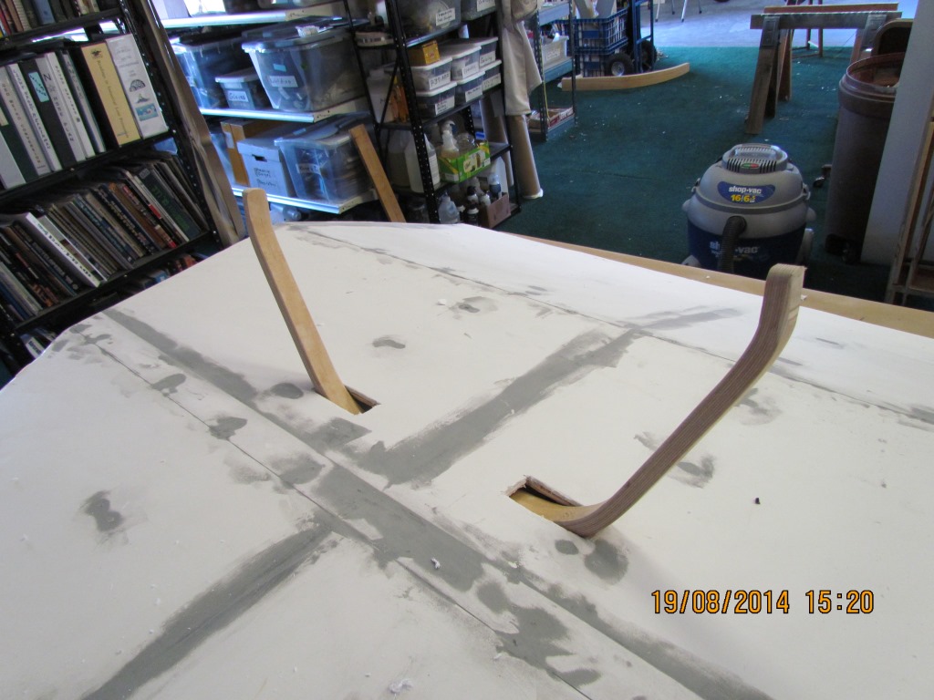
With the basic tubes in place, it was easier for the team to develop the landing gear and gear carry-through structure:
Completion ...
2015 - present
Once the tube structure was completed, the real work began! All the engine, control, and avionic systems had to be developed and installed. Additionally, 2020 was very disruptive to the project. So, this part of the project dragged on for some time. That is pretty typical with airplane builds: 90% finished, 90% to go!
I do not have a lot of photos to show at this point since this page is really about the tube structure construction. Maybe we can get Bob to post a detailed construction photo blog (this ultimately became his airplane).
FMX-7 Facetmobile Construction
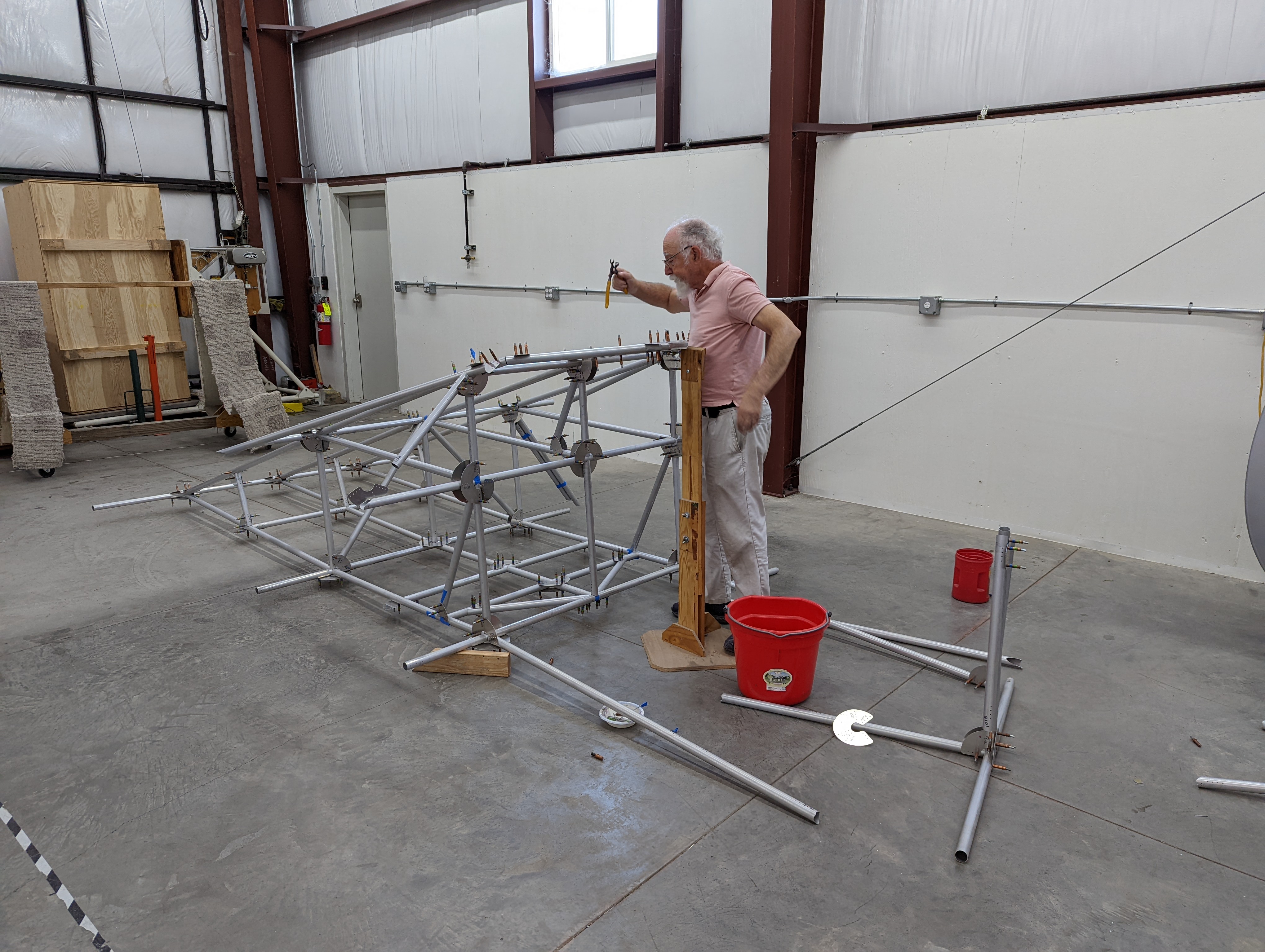
With Bob's Facetmobile mostly complete, work on Barnaby's FMX-7 began.
As noted at the beginning, this page is about the software and CNC used to fabricate the tube and gussets. It is not about the airplane. Maybe we can get Barnaby to post a detailed photo blog someday!
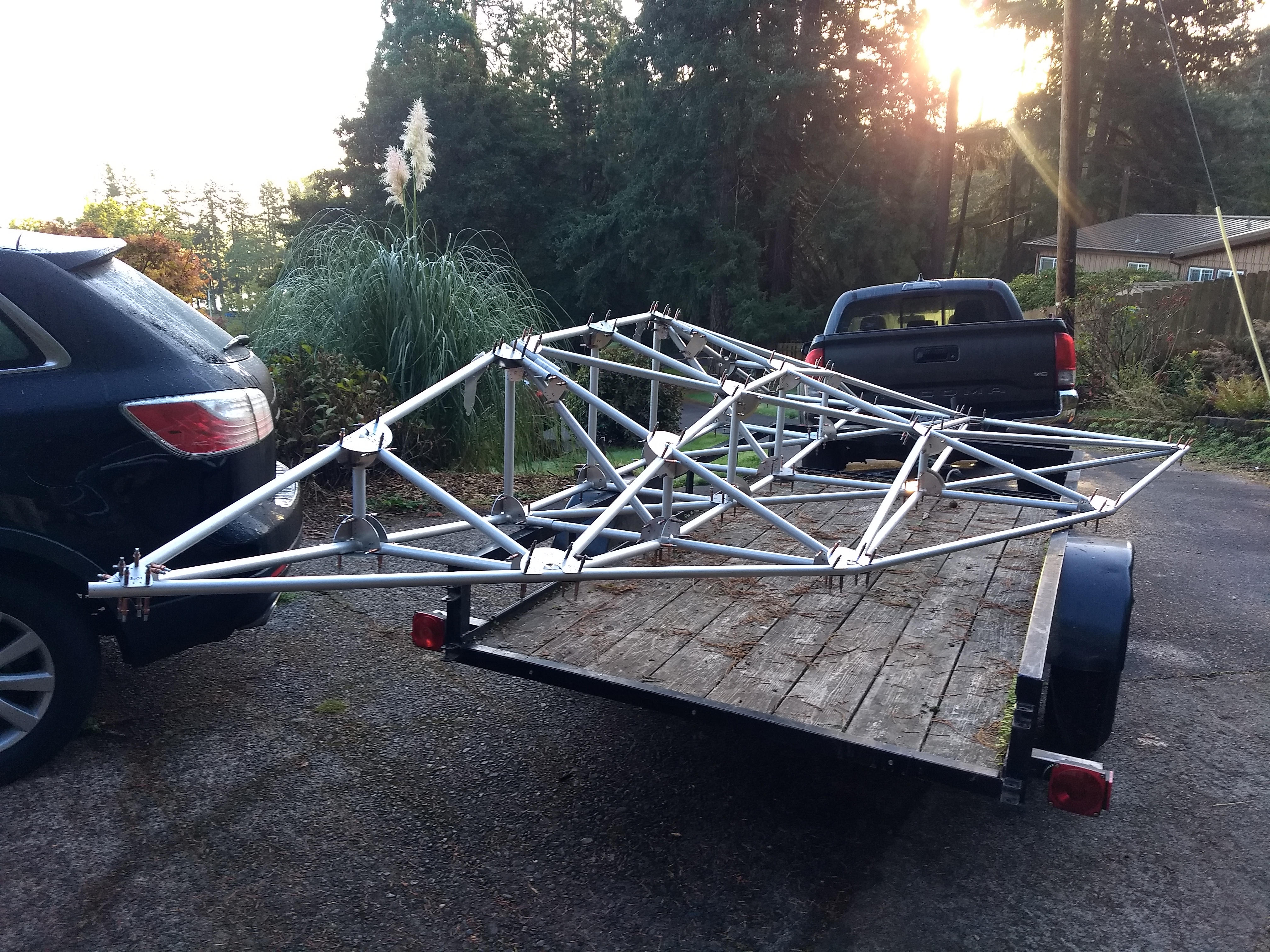
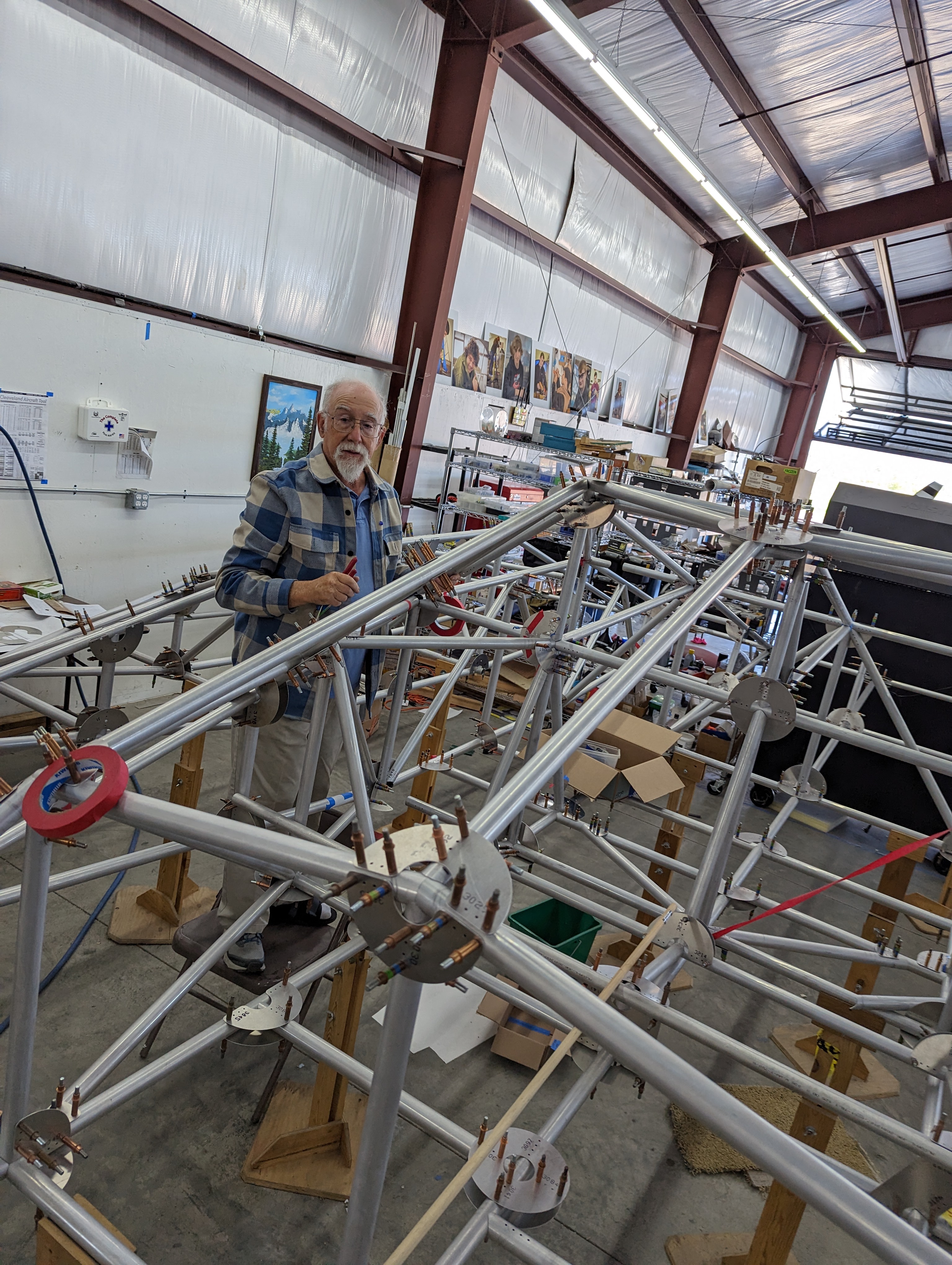
Regardless, the FMX-7 is a two-place version and is slightly larger. To accommodate the possibility of shipping a completed aircraft, the structure is built in three sections.
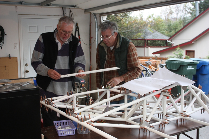
Getting Started
April 2021
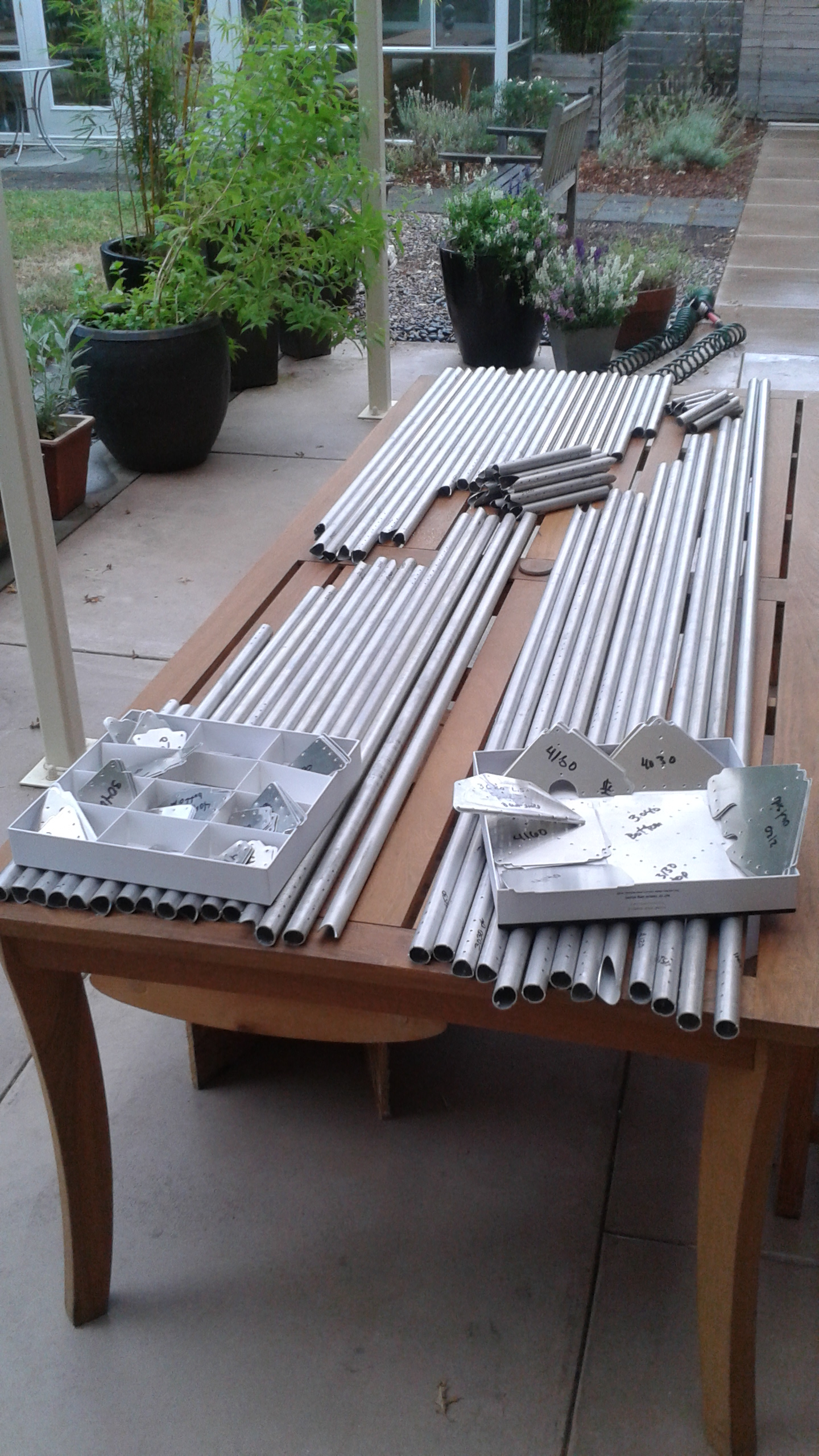
Tubes for one Facetmobile... some assembly required:
After a few hours, a small pile of parts:
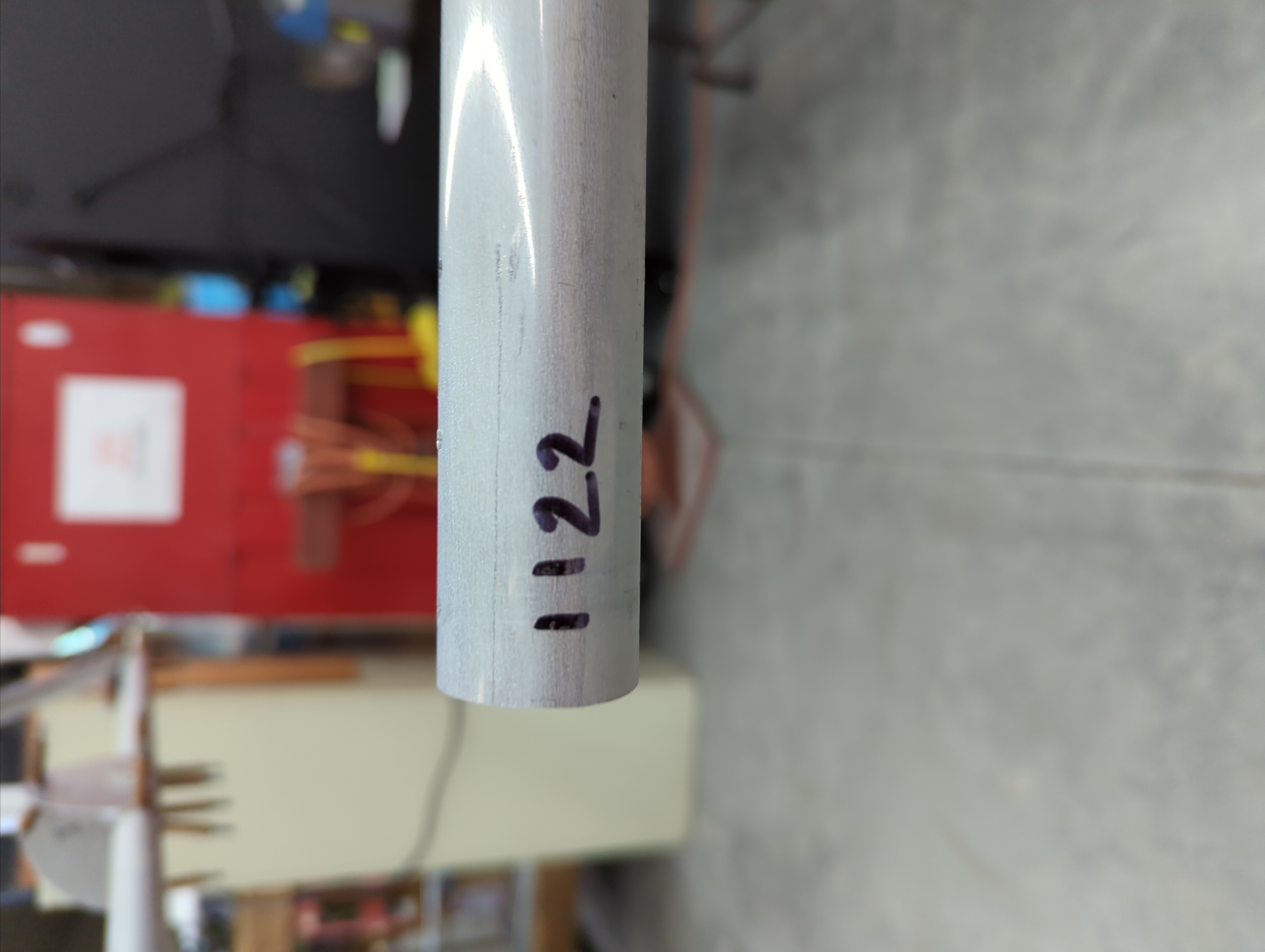
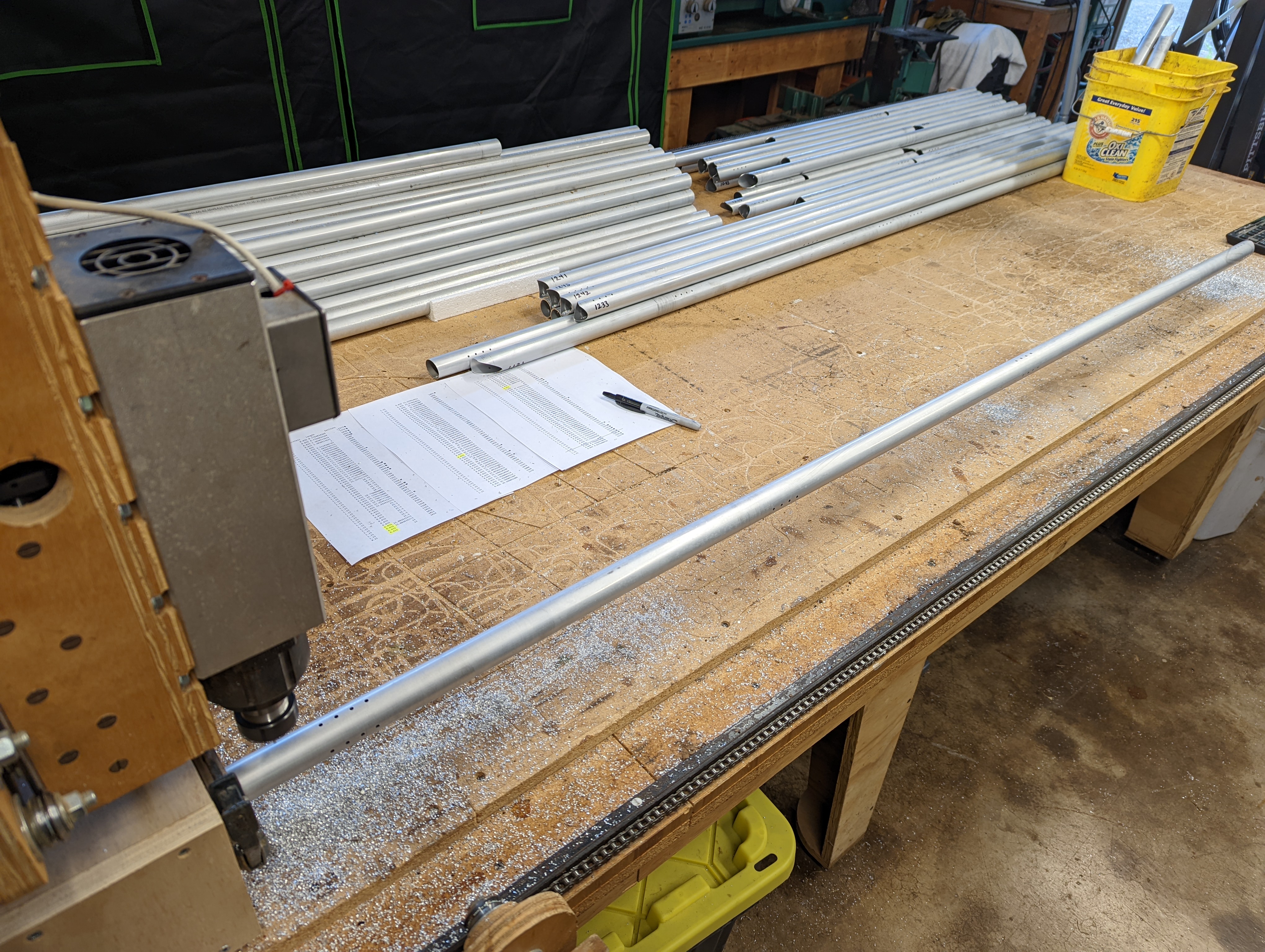
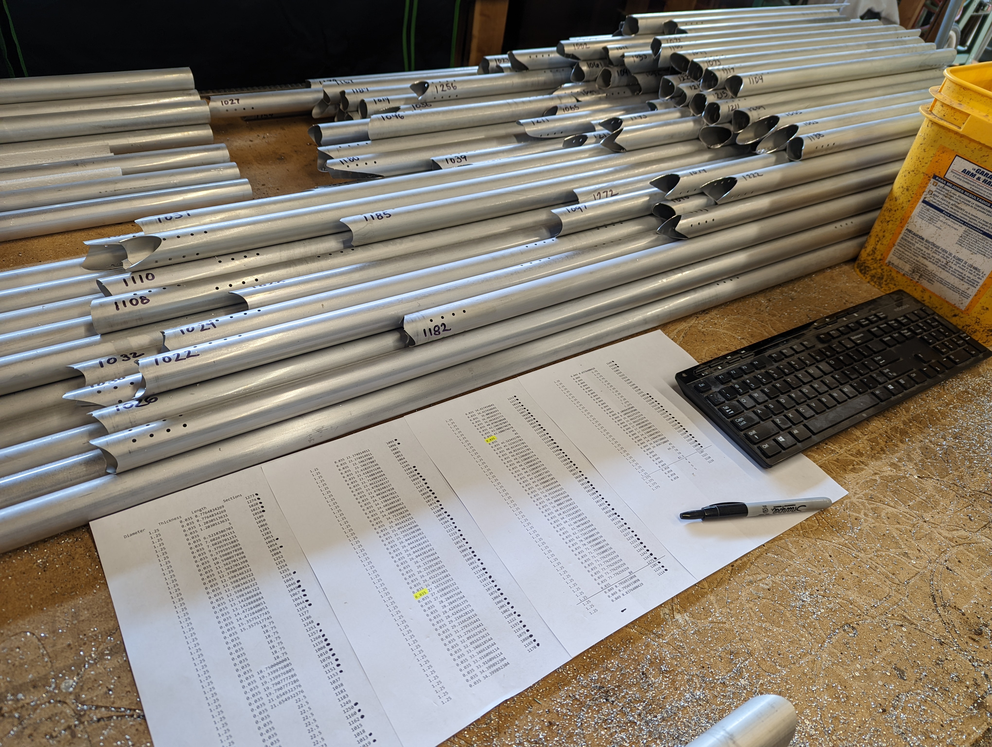
All tubes have a number. I would write this number on the tube on the front-top, so Barnaby could tell which, where, and orientation:
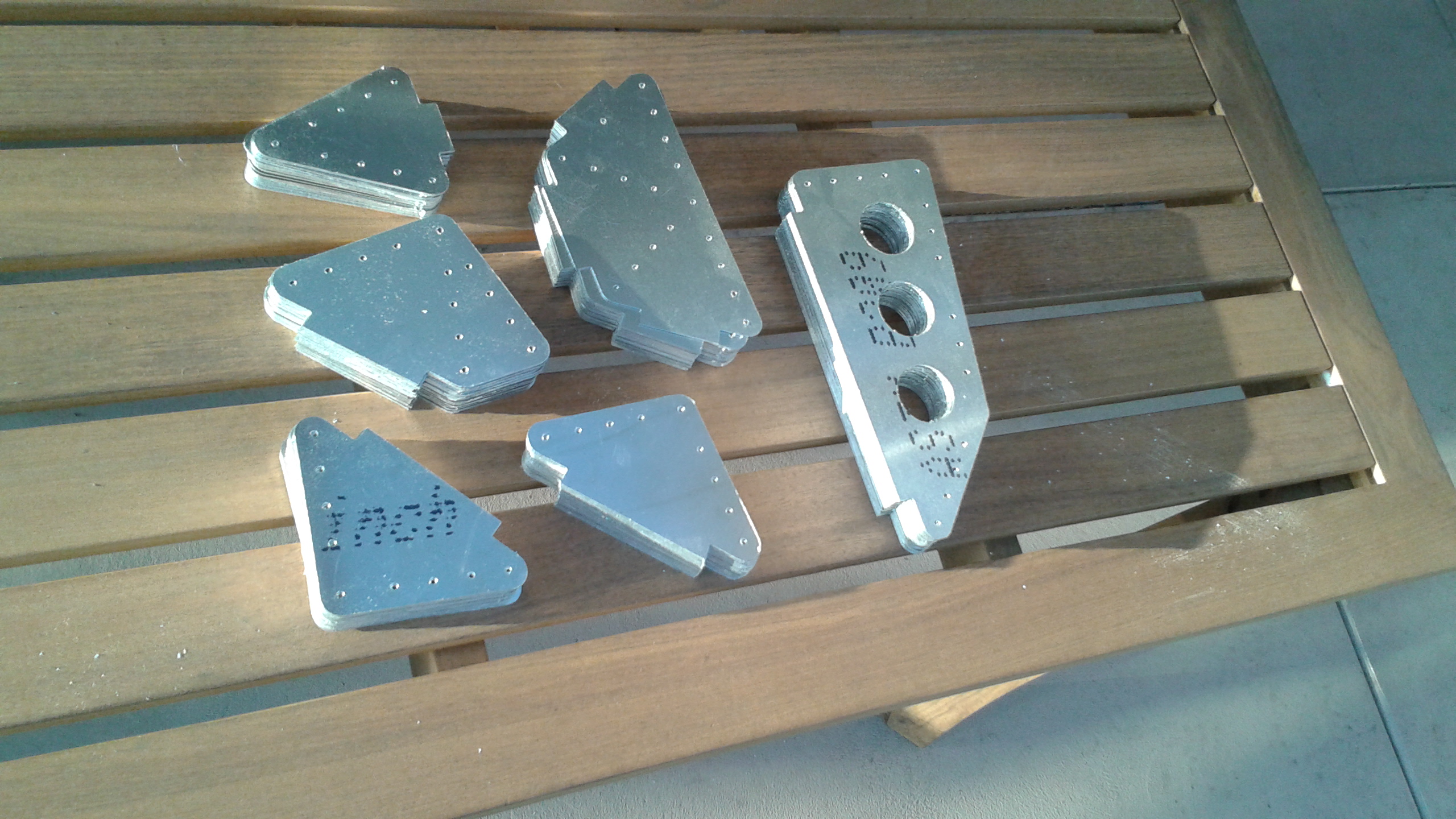
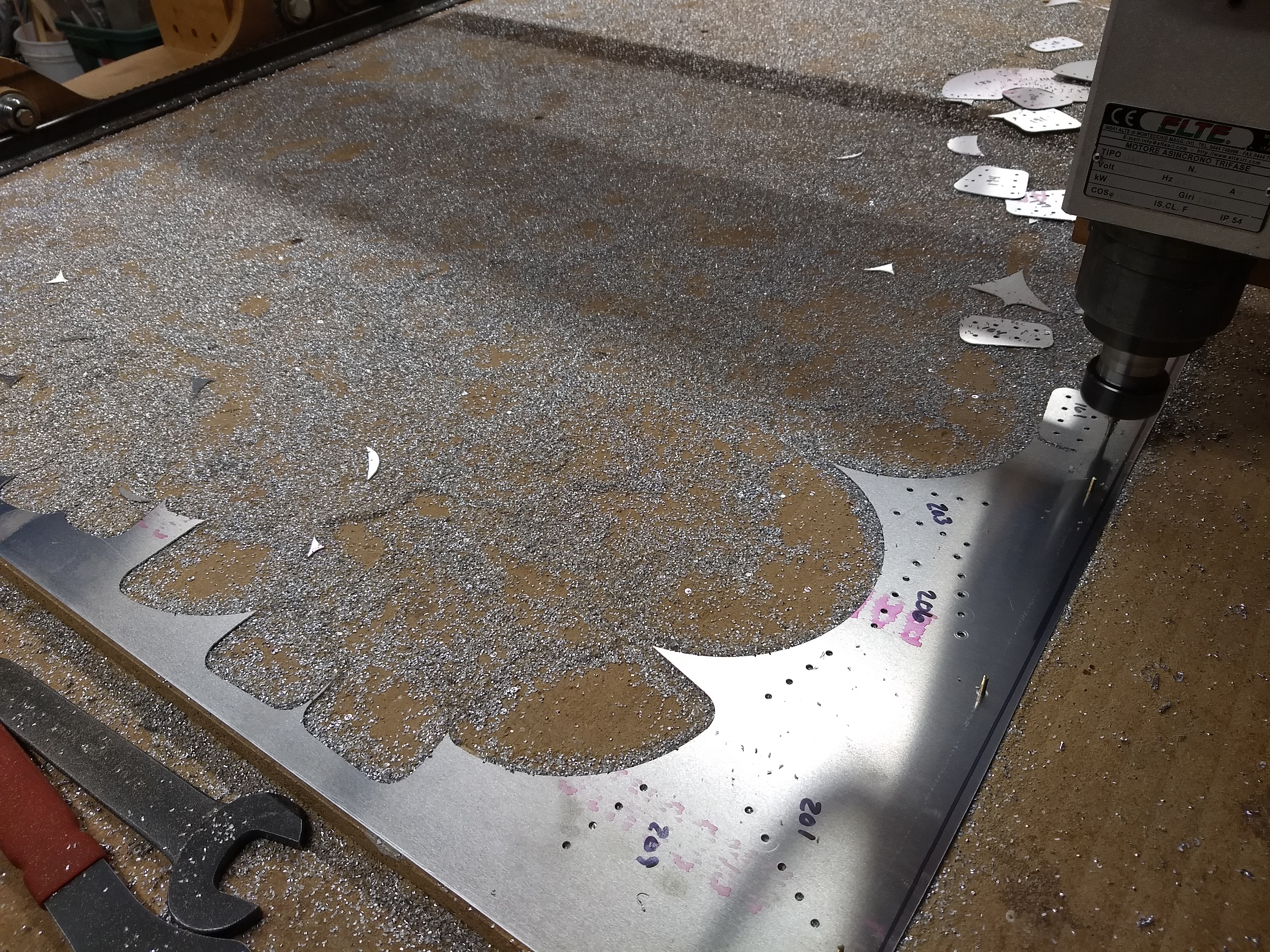
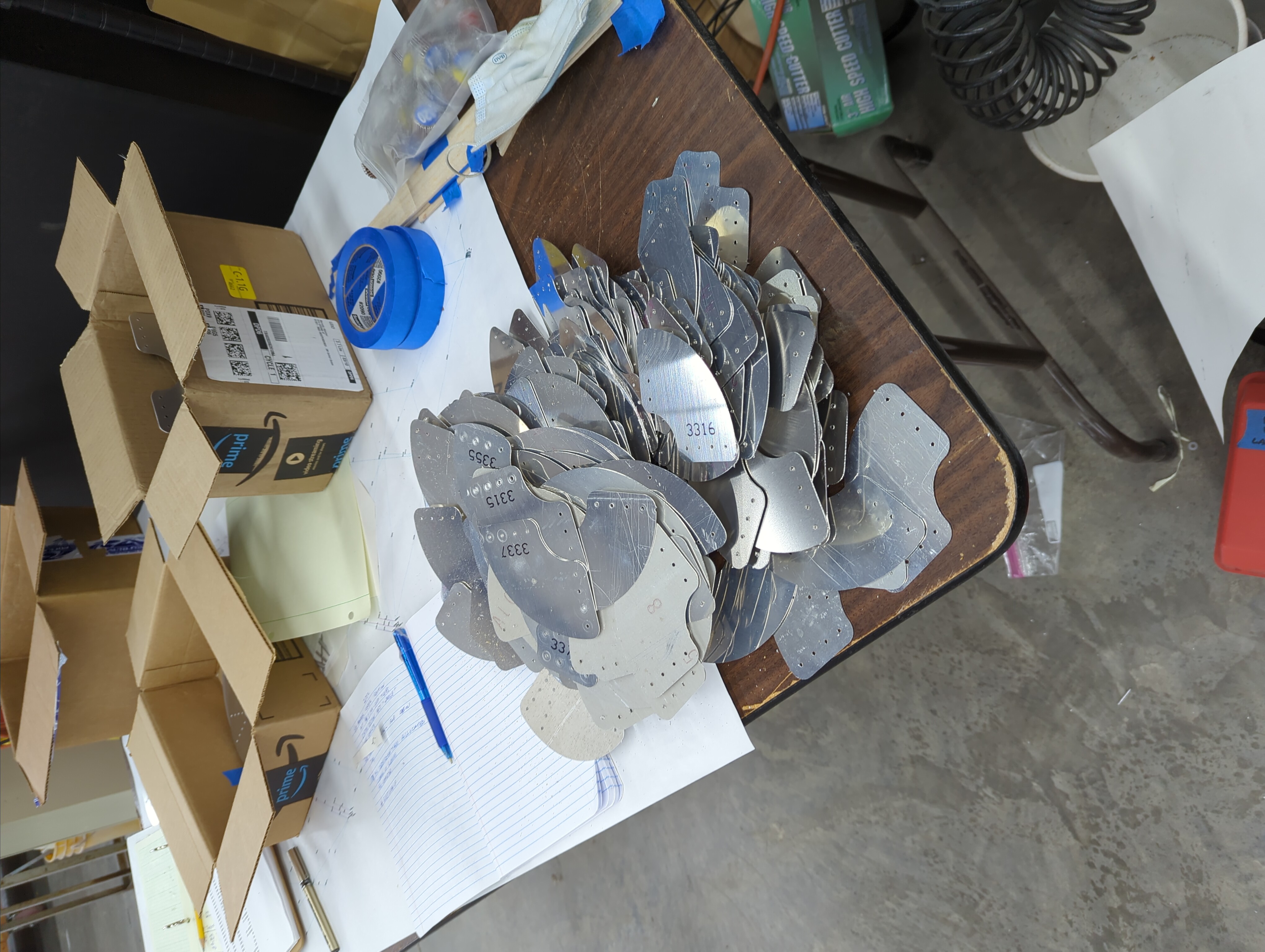
Gussets are as much a part of the structure as the tubes. The rivet holes were drilled first, then the gusset numbers were written on (I could determine where to write based on these holes), and then the gusset is cut out:
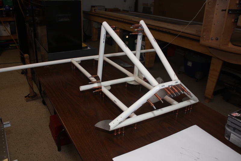
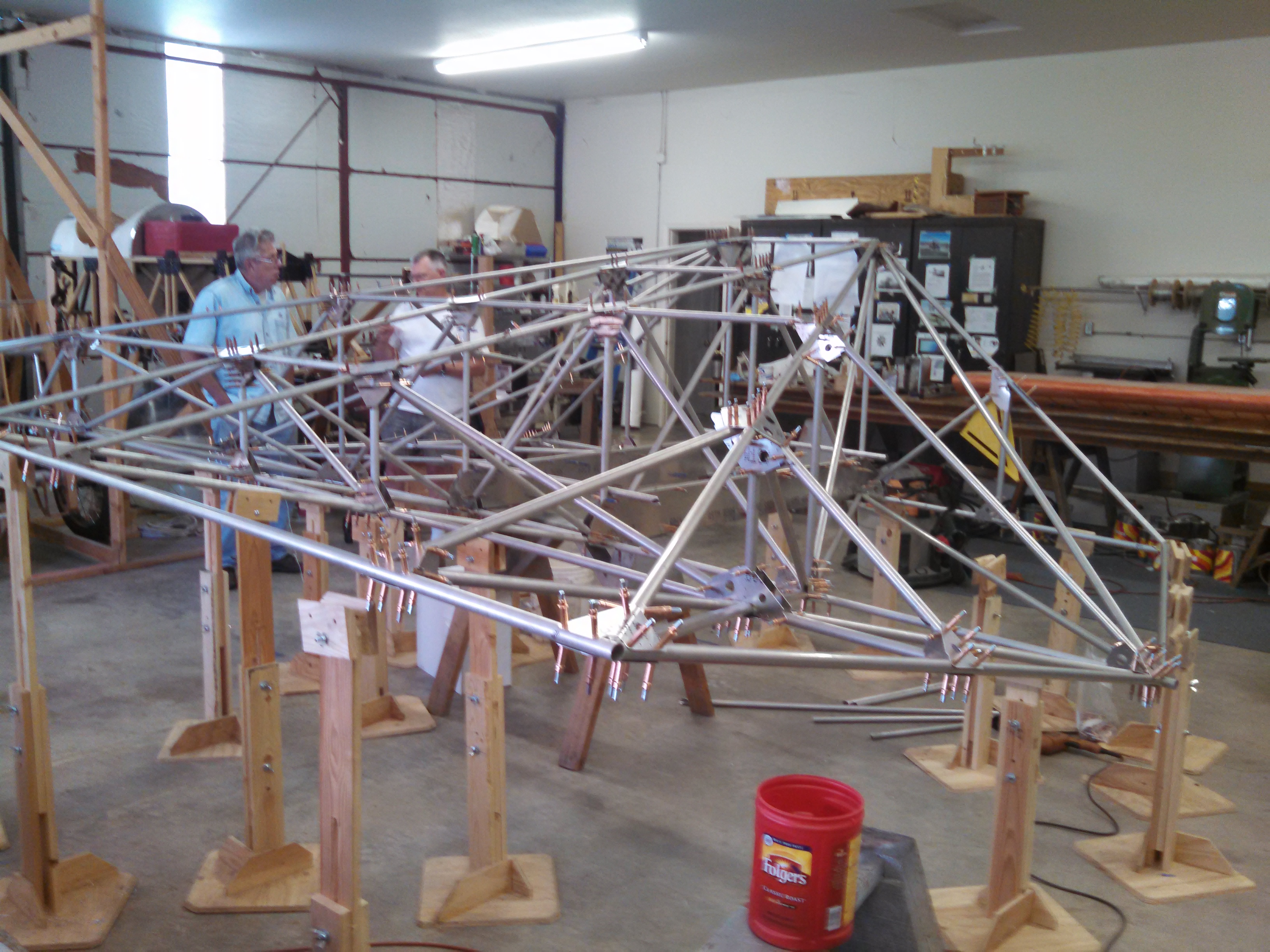
Left Wing
October 2021
At some point, I realized it was just easier to keep track of what was and was not fabricated simply by assembling the finished parts:
So as opposed to bringing Barnaby a pile of tubes and gussets, I just brought him a wing:
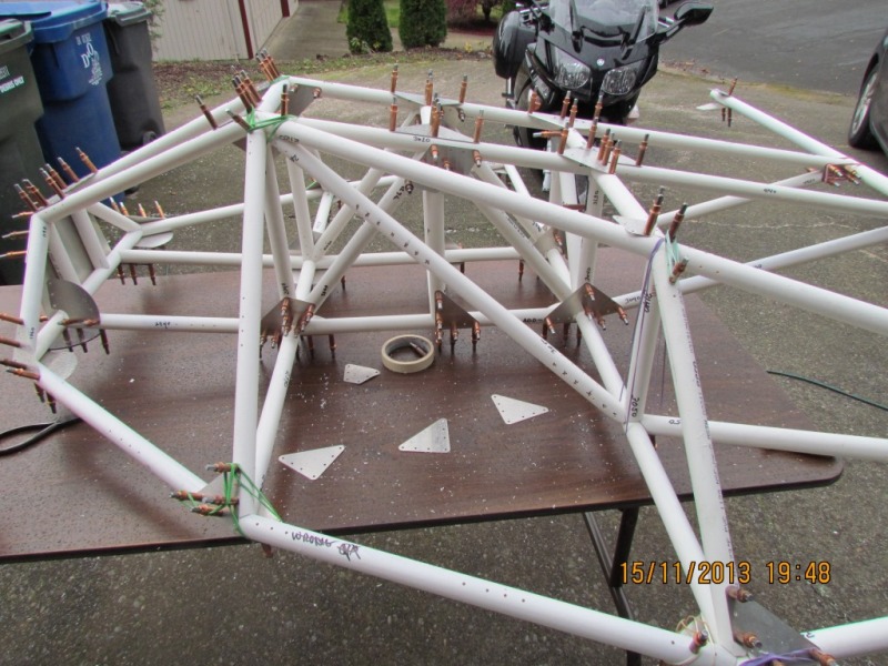
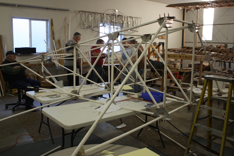
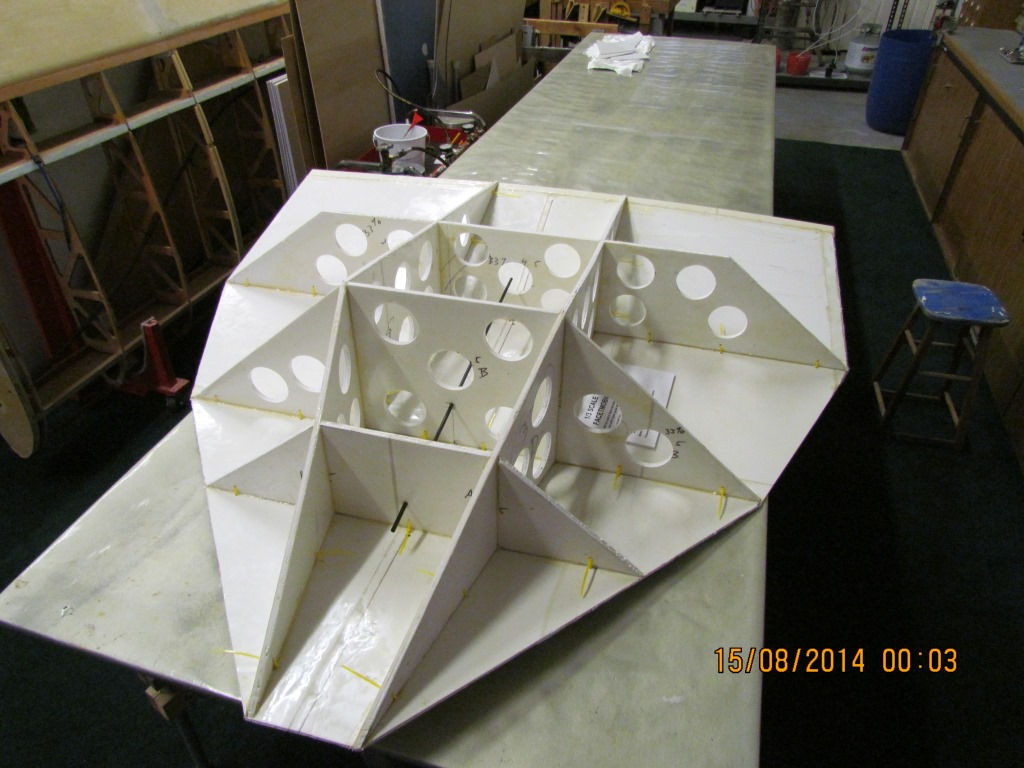
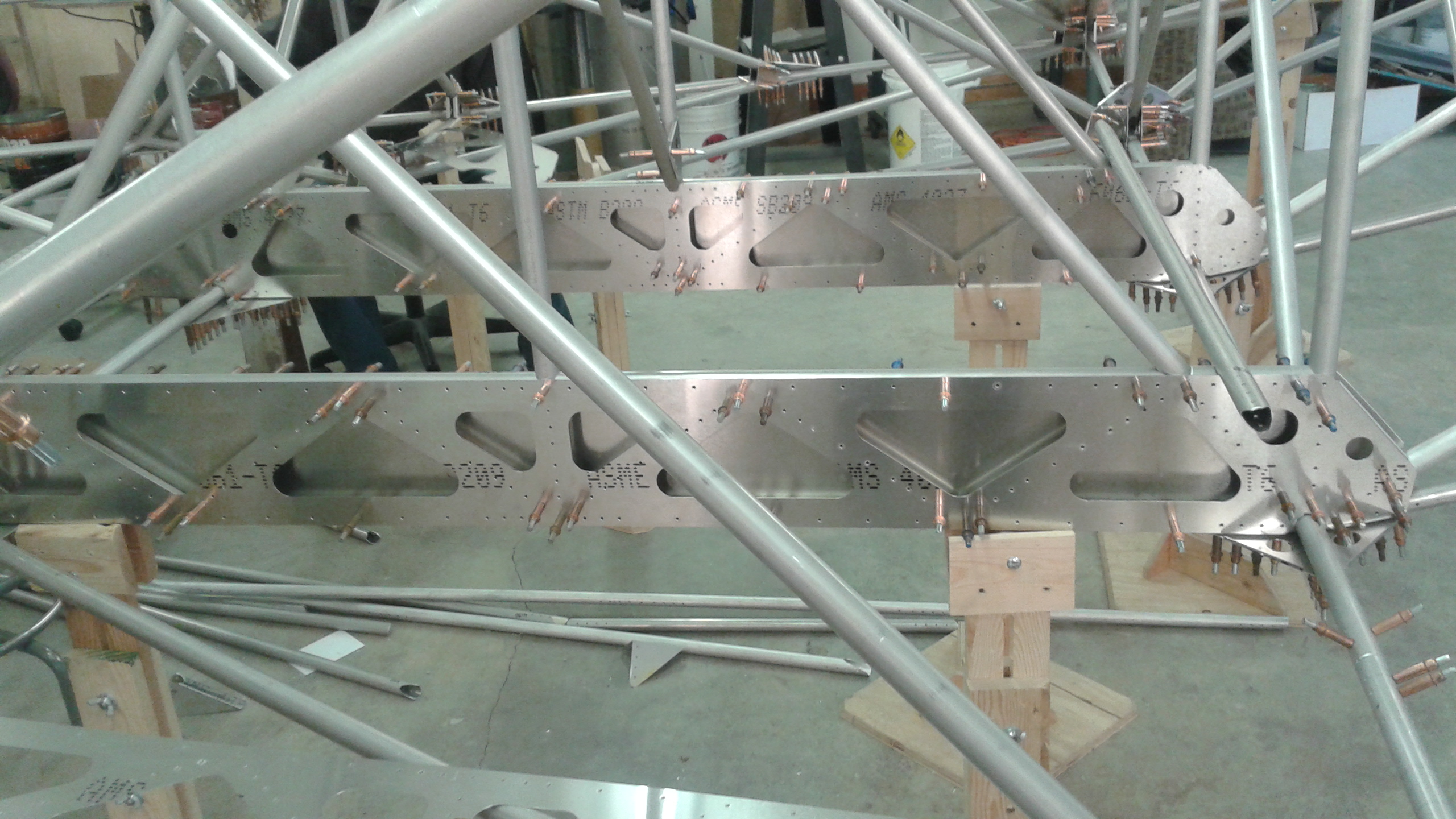
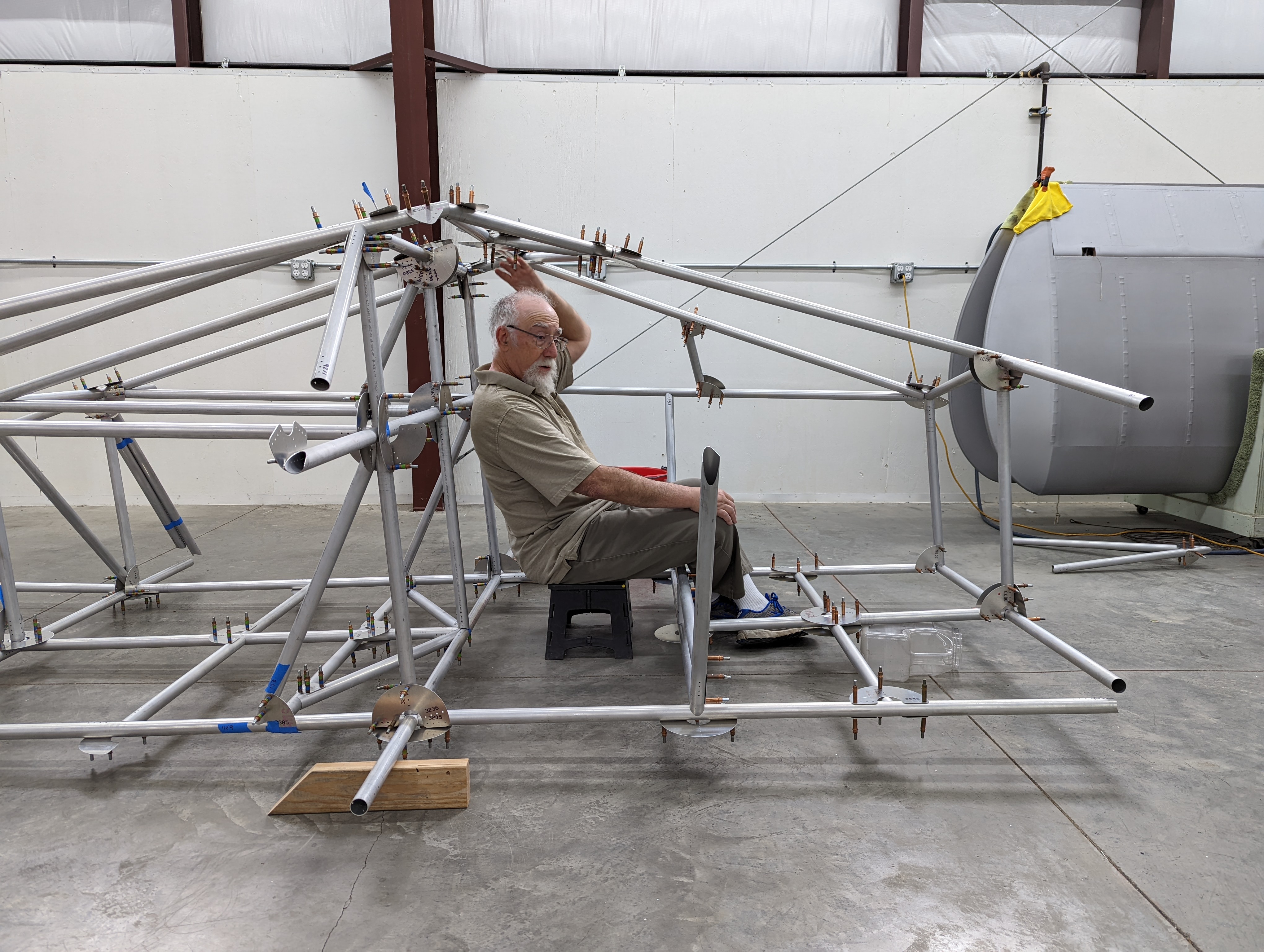
Center Section
May 2022
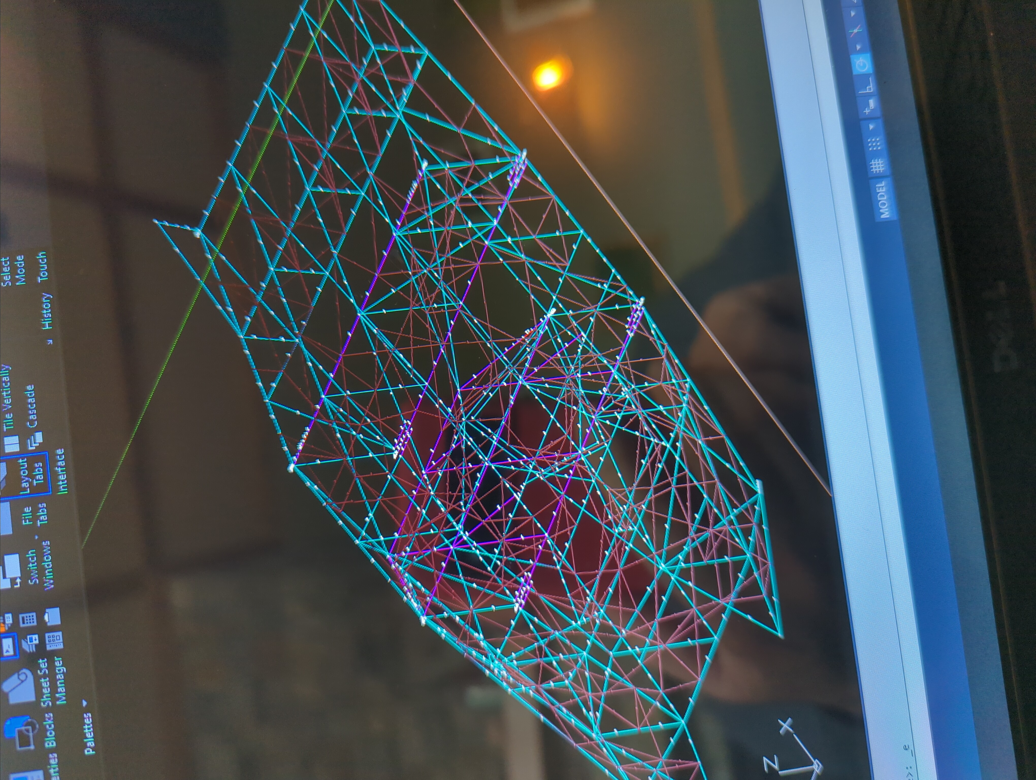
This image of the center section drawing shows what the custom software uses as an input. As you may see the tubes are represented by light blue lines. The thicker wall tubes are shown in violet. The gussets are actually drawn on as well, and are shown as the darker lines.
More CNC work:
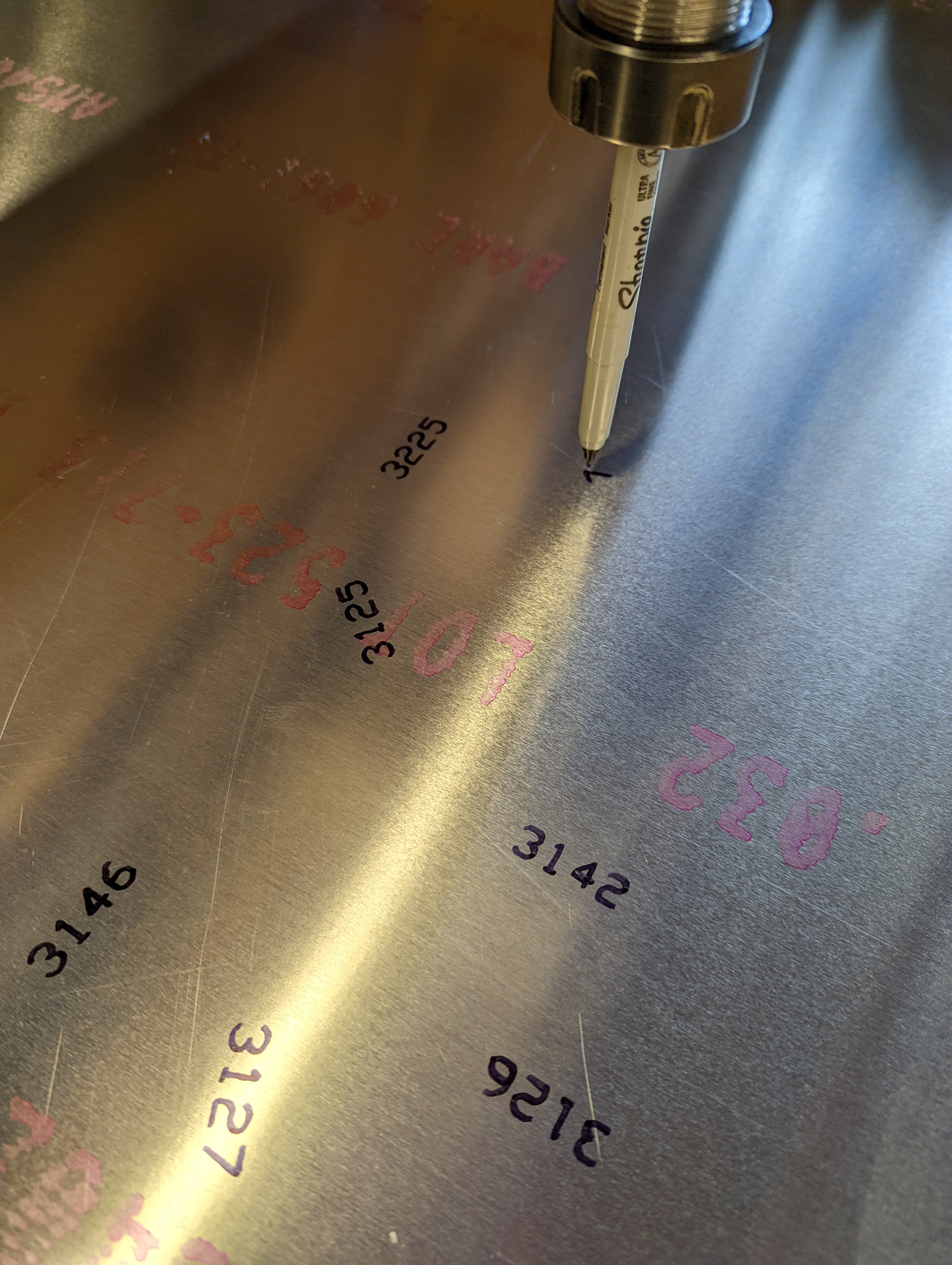
I got tired of hand writing the gusset numbers, so I just jammed a Sharpie in the CNC and made the CNC do the writing (I do not recommend this method, and I ultimately made a proper holder for the Sharpie):
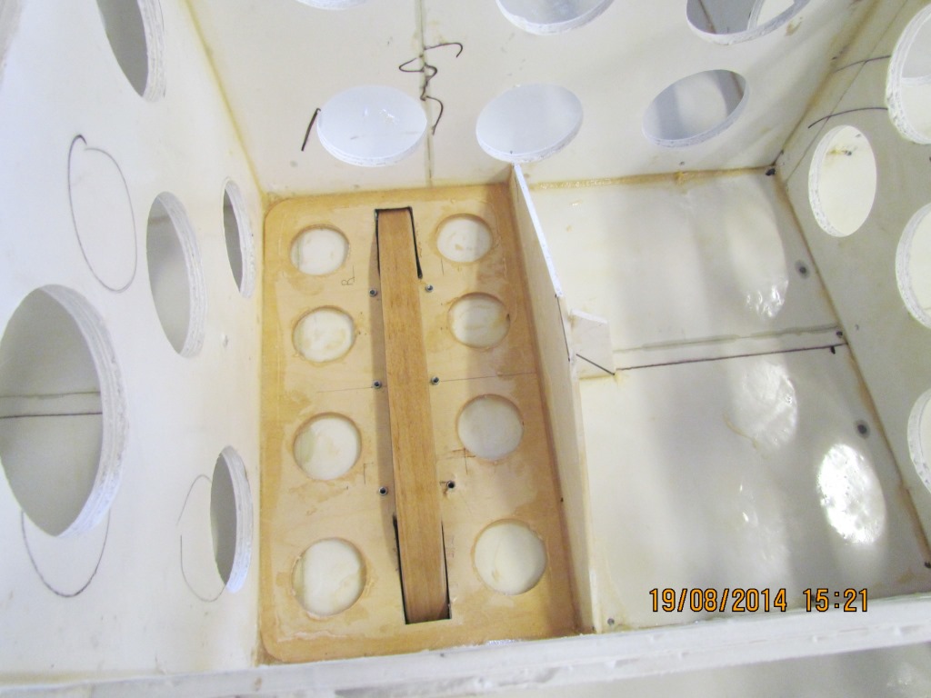
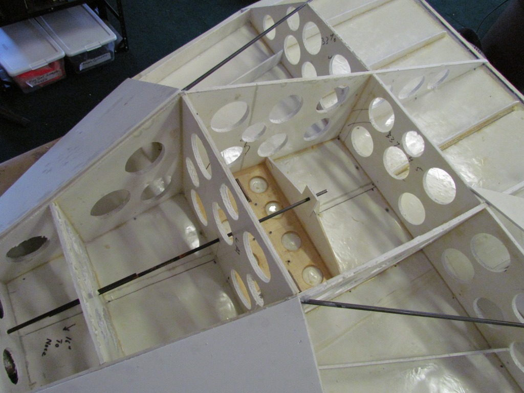
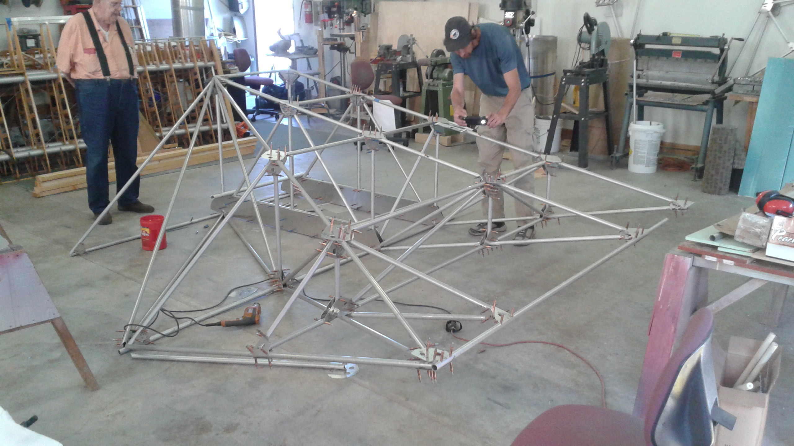
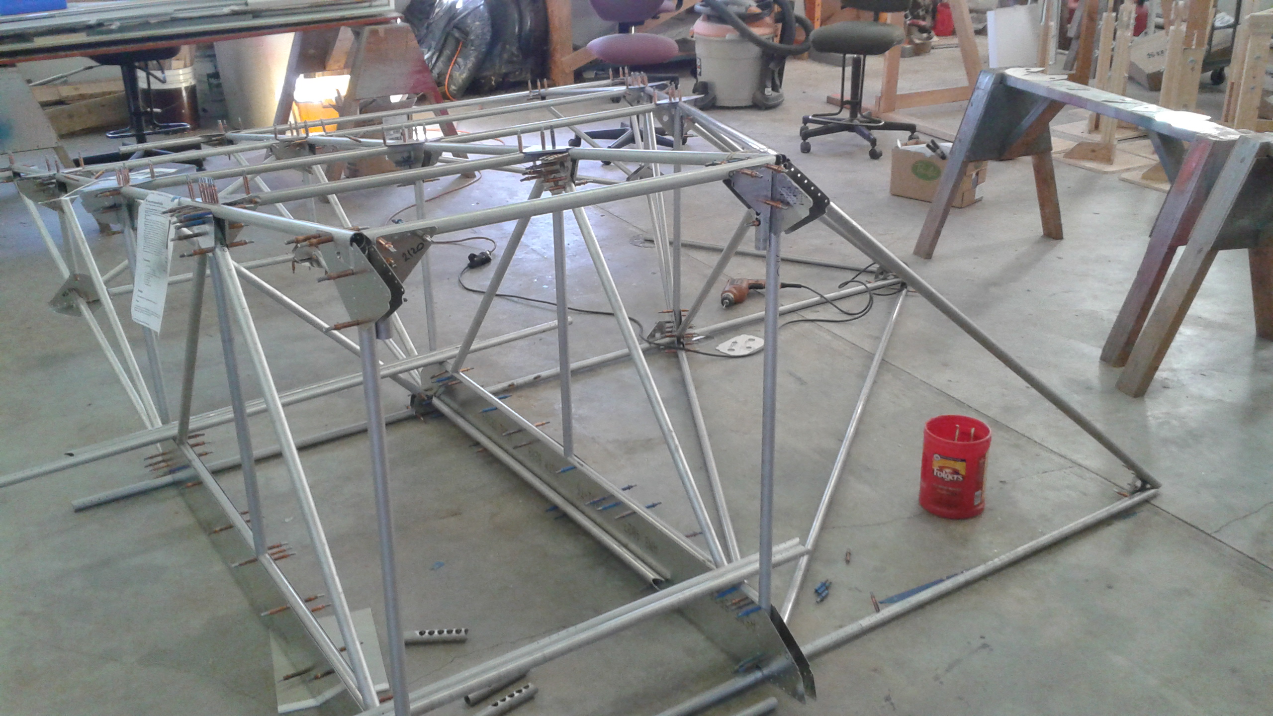
The center section assembly begins!
If you look closely at this picture, you can see Bob's fabric covered FMX-4 in the background:
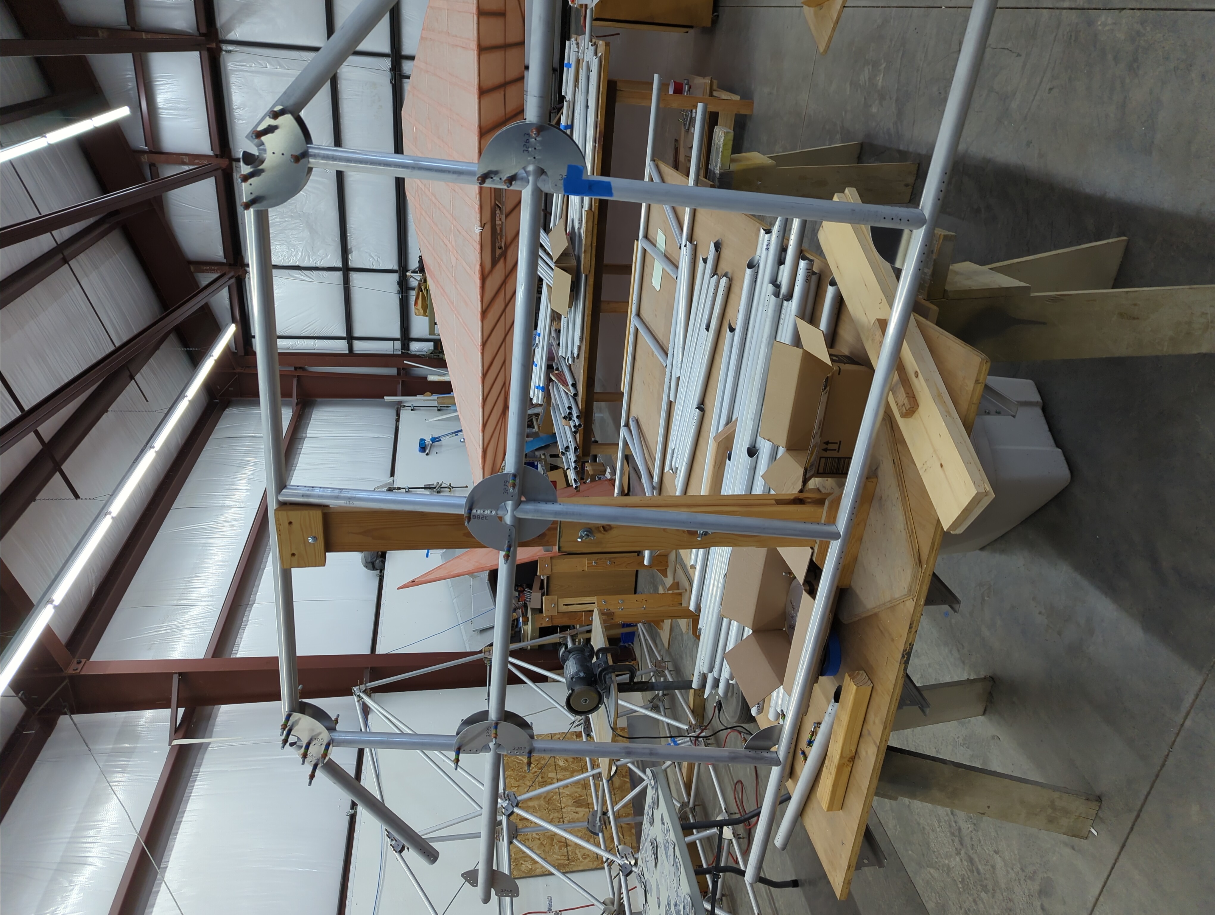
The center section was built and fine-tuned at the same time. Some changes were made along the way:
The upside to using a digital model, fabricating on a CNC, and automating much of it is that if an area needed to be stretched or whatever, making replacement parts became relatively easy. We did not have to modify very often; Barnaby's original design was really close at the first itteration.
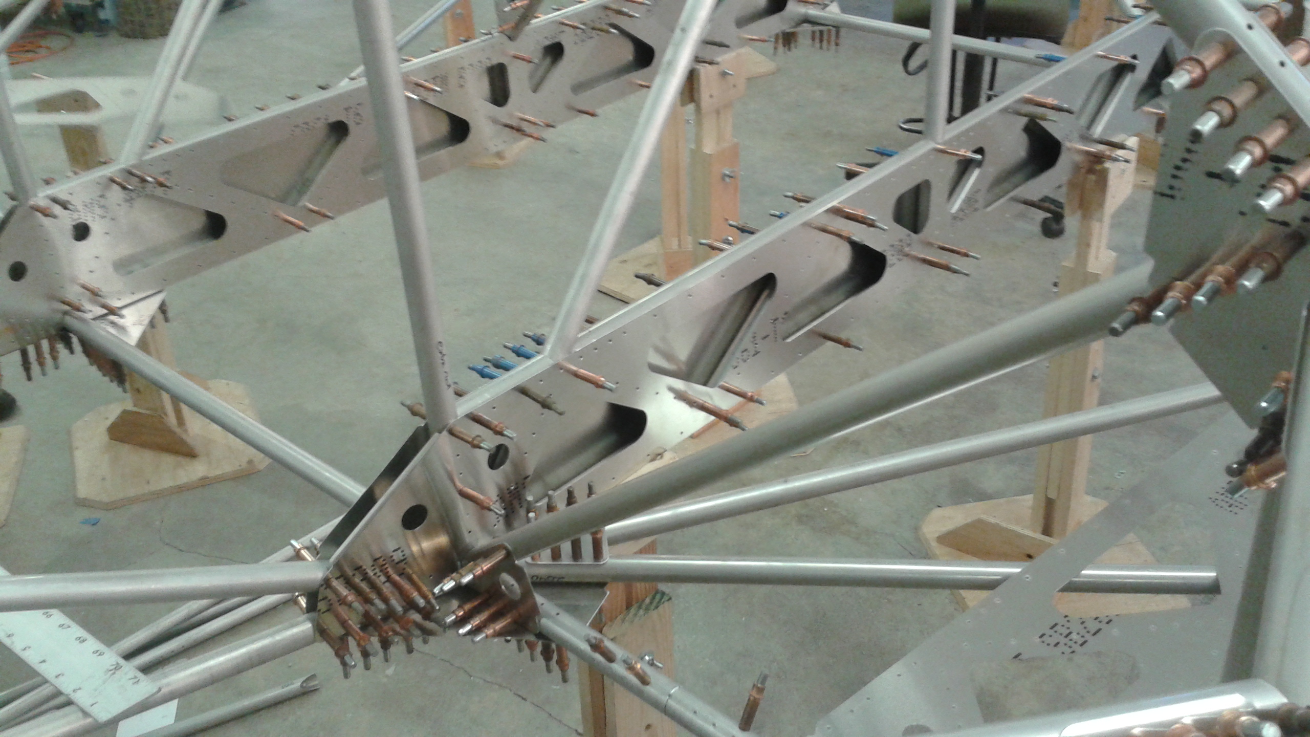
Gusset Details
A few words about the complexity of automatic gusset fabrication:
-
In software, a single gussets connects only two tubes. It is a simple triangle.
-
These are combined when necessary. Anywhere more than two tubes are connected the software had to combine multiple single gussets.
Below is an example of four gussets combined:
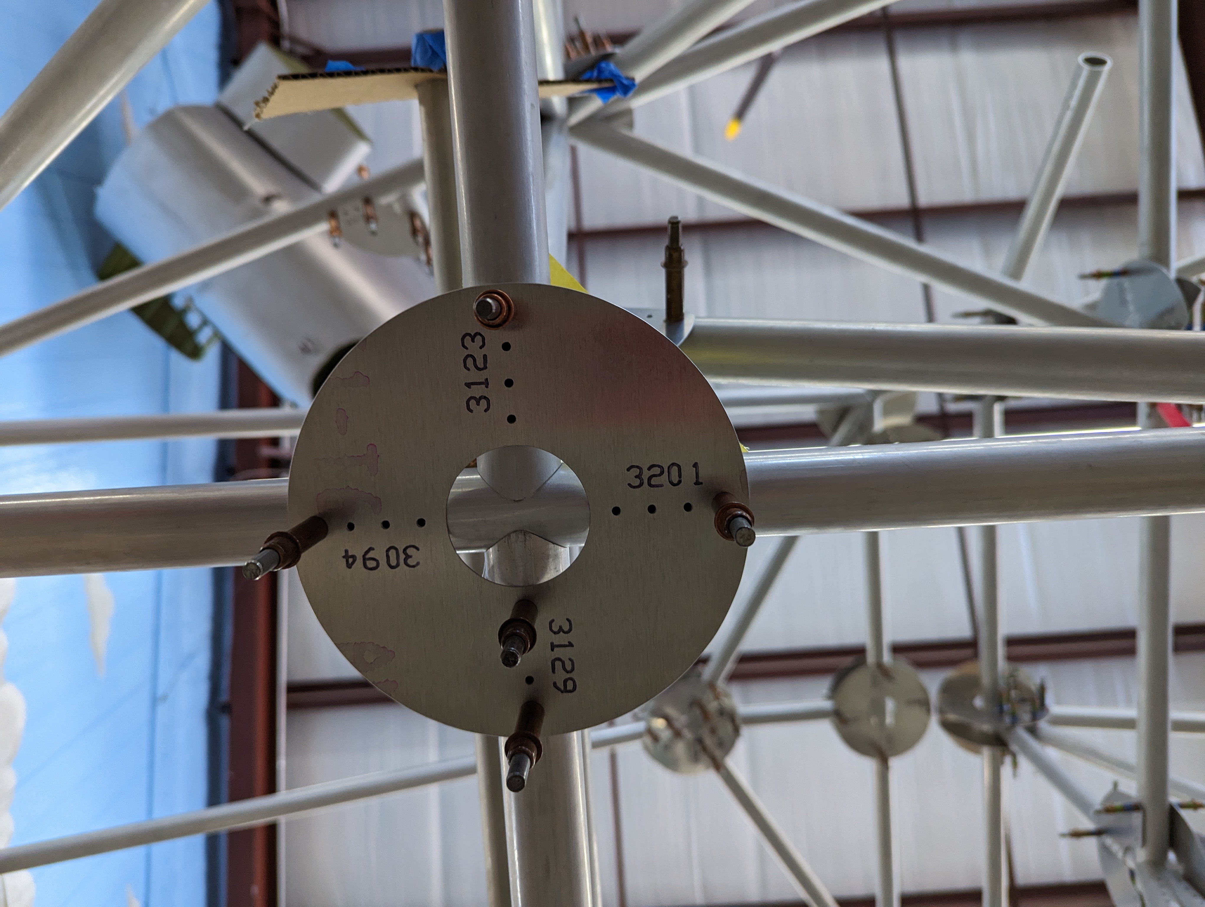
-
Even more complicated is when a combined gusset is not a flat surface and wraps around a tube. This requires some complex modifications, and the software automatically does this very accurately.
-
Gussets are better close to the end of the tube. But every once in a while one had to be moved out for clearance from something else.
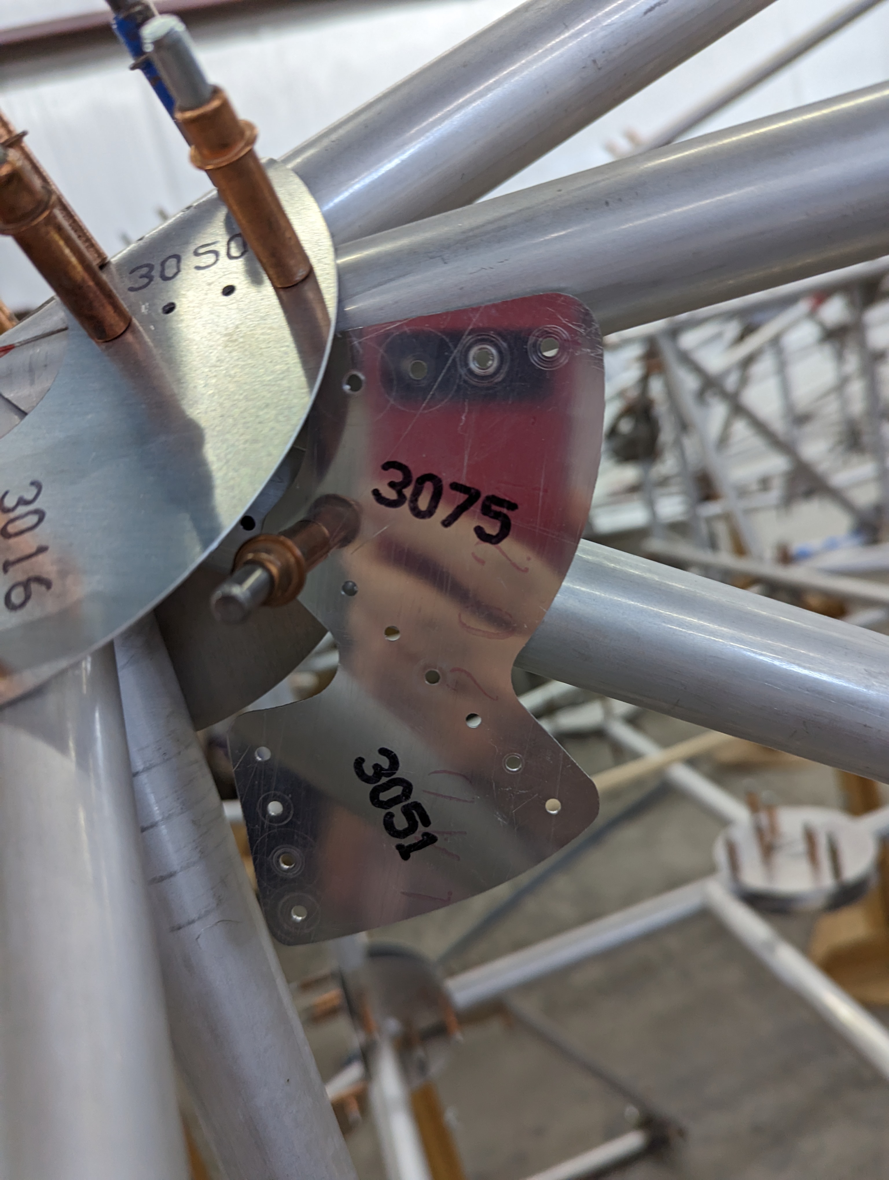
Below is an example of a really complex node. It shows multiple tubes clustered together, a wrapped combo gusset, and one of those really odd combos that have a normal and an offset gusset pair:
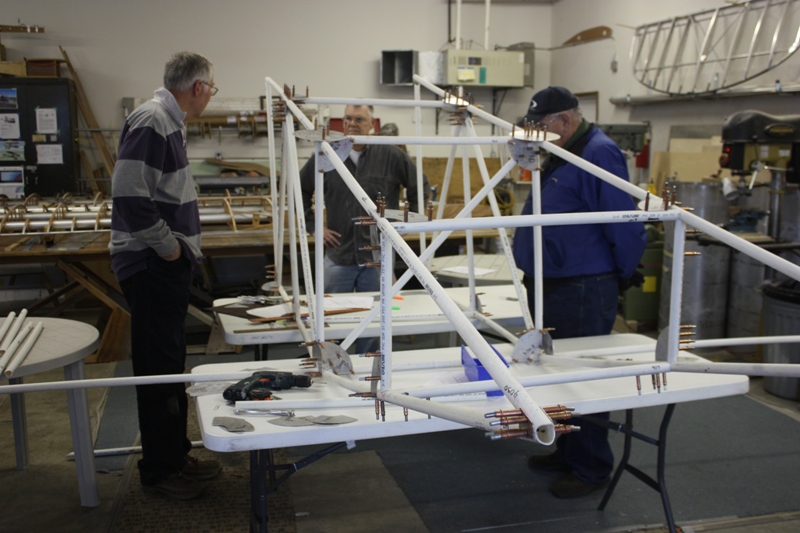
Right Wing
April 2023
The right wing went together almost like the left wing.
From a programming standpoint it was a little bit of a problem. At first you would think you could just mirror the left wing and have a right wing. Unfortunately it is a bit more complex...
To represent a gusset in CAD I used a line which was drawn between the midpoints of two tube lines. Riveted gussets are not centered between the tubes like a welded gusset; they are on the outside surface and either on one side of the tubes or the other. To determine which side, it depended on how the CAD line is drawn. We used the right-hand-rule. If the line was drawn starting on tube-A and ending on tube-B it was on one side, and if drawn in the opposite direction it was on the other side. The right-hand-rule determined which side.
... So if you mirrored the left wing to the right wing, all of the gussets were on the wrong side! No big deal: Just sit down at a coffee shop and redraw all of the gussets for the right wing. It took me an hour, two cups of coffee, and one Marionberry scone.
Barnaby captured by the right wing:
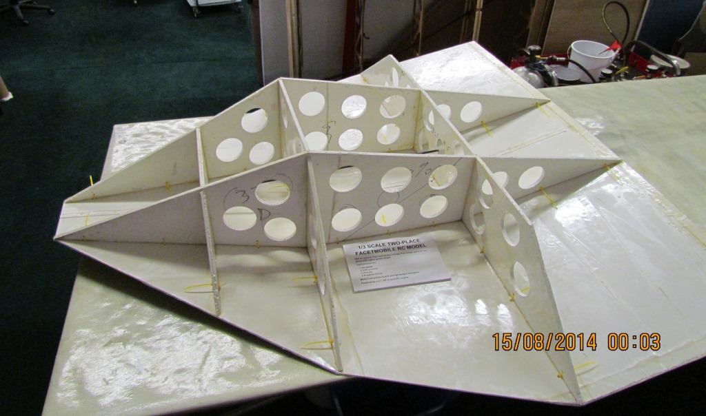
All three pieces together, and the little RC model sticking around for inspiration:
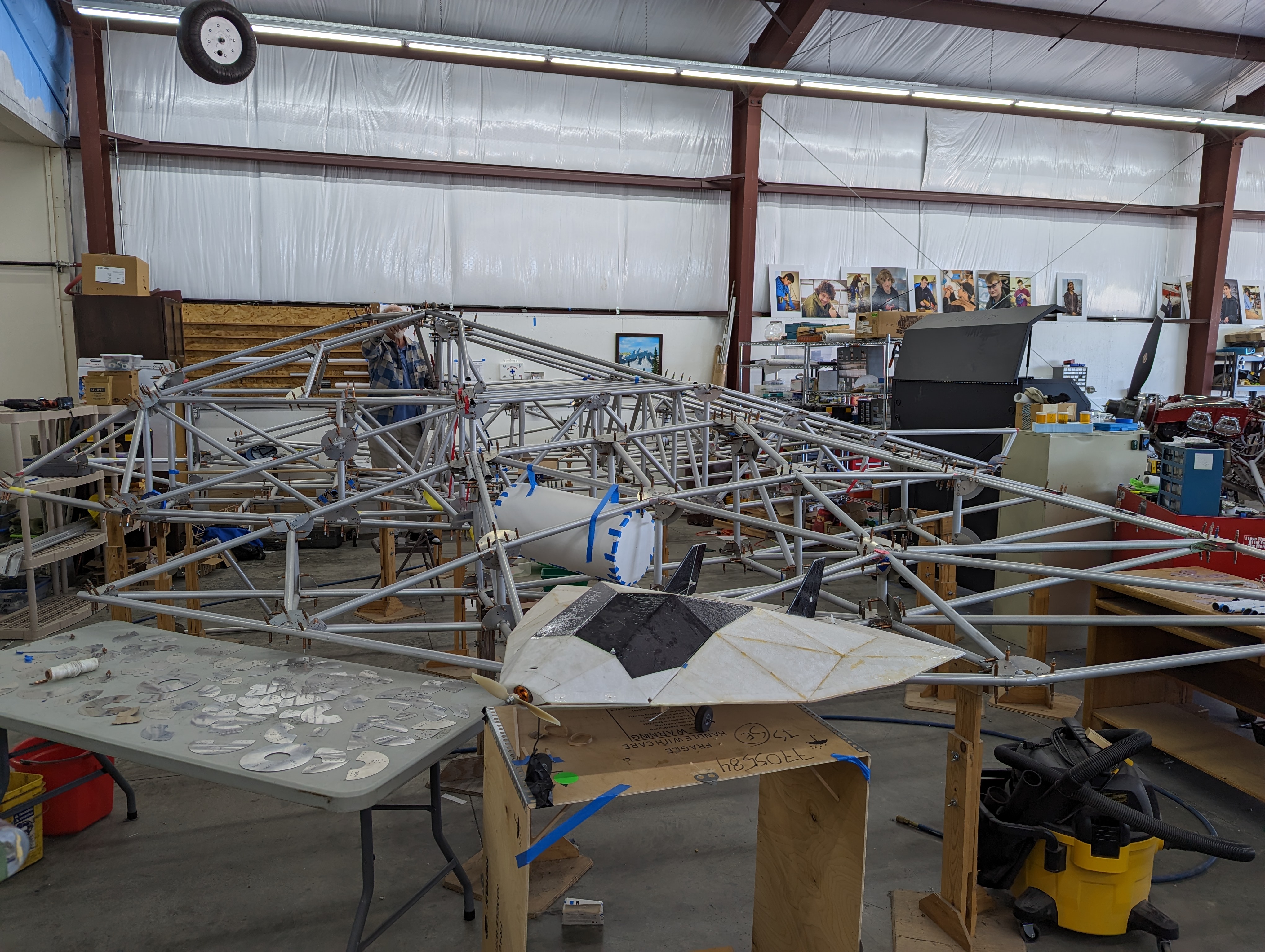
Sure, there is a lot more to show about the FMX-7, but that is about it as far as tube and gussets are concerned. I hope you enjoyed this page.
Thanks!