Legal Eagle Ultralight
The following is a photo album of the construction of my Legal Eagle Ultralight, plans #T57. This is the standard design (not the XL version), with a cut-case 1/2 VW engine. The details of construction are mostly shown in the images below, but I tried to add notes where I thought it might help others building a Legal Eagle Ultralight.
My Legal Eagle Ultralight was scratch built using the plans from Leonard Milholland, and if you are also interested you can get them here:
- Legal Eagle Ultralight
- Legal Eagle Component Weights
- Wing Ribs
- Wing Spars
- Wing Assembly
- Wing Leading Edge
- Engine
- Fuselage
- Seat
- Tail #1
- Fuselage Details
- Powder Coat
- Instrument Panel
- Tail #2
- Tail Skid
- Ailerons
- Wing Covering
- Latex Paint
- Almost Finished
- Pretty Pictures
- Windshield
- Legal Eagle and Thatcher CX4 projects
- Taxi Test
- Flight Test
- Initial Revisions
- Engine Mount Bushings
- Brakes
Legal Eagle Component Weights
At every phase of the construction, I weighed the assembly, part, component and wrote that down. I have compiled that into a spreadsheet, which is here:
Legal Eagle Component Weight Spreadsheet
For example, I went as far as weighing the wings as just wood, then after varnish, then after covering, then after tape and stitching, and then after sealing and paint. It was a bit over the top, but hopefully this is useful for future work.
Wing Ribs
2014 August
Stick-built wing ribs were construction in a traditional fashion using a jig. The rib outline was plotted on paper, glued to a flat board, and then positioning sticks were nailed over.


The top and bottom cap strips were the first to be positioned in the jig. Then the interstitial sticks are trimmed and sanded to fit exactly. Those sticks are glued in, the joints are covered with gussets which are glued in, and then small construction staples tacks it all together. The staples are enough to hold it all so the rib can be removed from the jig, and then the next rib is started.


When the the glue is dried on a batch of ribs, the staples are removed. The rib is flipped over and the gussets are glued to the opposite side. When that glue is dried, the ribs are sanded.

Wing Spars
Spars were made of thin plywood with wooden top and bottom cap strips epoxied on. We used our CNC router to cut out the plywood resulting in very clean and accurate cuts.


Wing Assembly
2014 November
The ribs and spars were construction so that the ribs could slide over the spar. Once positioned, the ribs were epoxied into place.


Every once in a while the fit was so tight that a little bit had to be filed off.


Wing Leading Edge
The wing's leading edge is formed with plywood nose ribs. We cut those ribs on the CNC.


One of our CNC tricks is to drill 3/32 inch positioning holes, and then use small pieces of 3/32 inch welding rod to hold the plywood in place. Then, when the parts are cut the piece stays in place when it is cut free from the stock material.

Engine
2017 November
We used a cut-case 1/2 VW engine from Hummel Engines.
There are two engines in the following picture.


Cafeteria trays make great part trays.


A completed engine.


Fuselage
The fuselage was built at the EAA-292 build hangar.

2017 December
All the 4130 tubes were cut and ground to fit by hand, and then TIG welded together.


The wings were located so that the upper portion of the fuselage could be fabricated to match.


Seat
2018 January


Testing the seat:

Tail #1
2018 April
The first tail was build exactly to plans. The problem that was encountered was that the hinge locations are not immediately next to a spar, and when any sort of tension is applied by the fabric covering, the hinges are no longer aligned. I found this out later in the build.


Fuselage Details
2018 August


Powder Coat
2019 January


Instrument Panel
2019 June
The first instrument panel used electric gauges. These were powered by a 14 volt RC battery. Even after using shielded spark plug cables, the electric noise and the lack of a substantial ground sink caused problems with these gauges. These were all replaced later with mechanical gauges.


Tail #2
2019 September
The first tail was covered. After this, it was immediately apparent that they would not work since tensioning the fabric pulled the hinges out of alignment.


2020 January
A second set of tail surfaces were redesigned and fabricated, and the hinges were positioned up against ribs.


Tail Skid
2020 February
In an effort to keep things light, a laminated wooden tail skid was fabricated. This arrangement ultimately worked, but a couple had to be prototyped (broken). Also, the initial layout used a skid and skid plate, but this arrangement only is appropriate for grass strips. The friction on the asphalt ground off the plate immediately.


Ailerons
2020 April


Wing Covering
2020 November
The wings were covered in uncertified lightweight fabric, glued down using 3M Fastbond 30NF (water based), rib-stitched using the Superflite Knot method (one side at a time), with the fabric sealed and covered using latex paint.


Latex Paint
Sealing and painting the fabric covered wing was done with latex house paint. Sherwin Williams latex paint was used as a sealer / UV covering. Another EAA-292 member performed a decade-long UV exposure test using latex covered Dacron with satisfactory results. Regardless, this aircraft has been kept in a hangar not exposed to sunlight... it should last my lifetime.
Since sealers / paints do not adhere directly to Dacron fabric (it is a plastic) the coating is actually held mechanically. It requires a paint layer below and above tied together through the fabric, not just a coating on top. So tests were performed to determine how thin the paint needed to be to just bleed through the fabric and coat the inside thoroughly.
Using several different mixes, it was determined a 2 parts paint to 1 part water for the first penetrating coat provided acceptable results. This was applied with a 4 inch foam trim roller. This is a very thin mix and care should be taken not to squish the roller and get paint everywhere on the inside of the wing.
After that, a 4 to 1 ratio worked well for building up after that first coat. The goal is to make these just thin enough to be smooth and not look like the outside of a house. The top of the wing received three build coats, and the bottom received two.


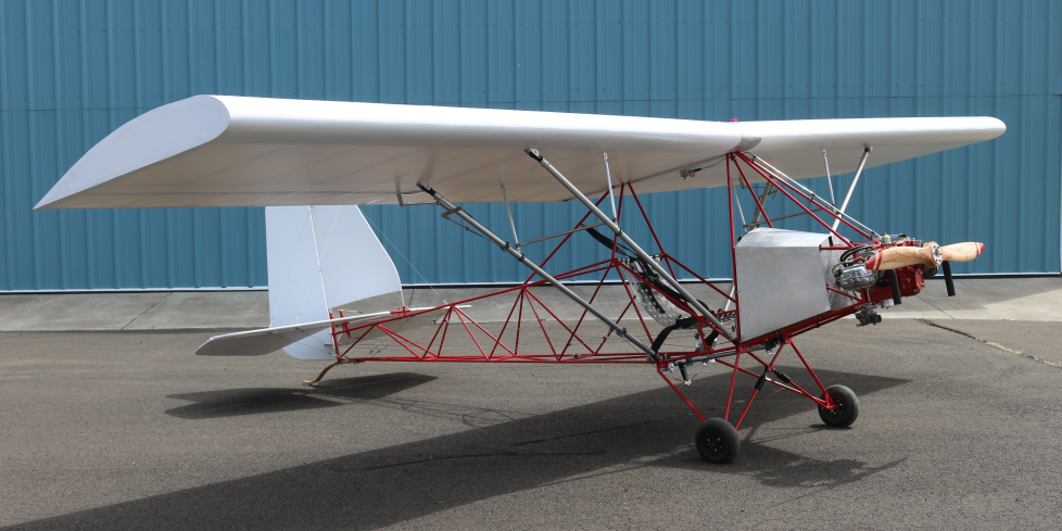
Almost Finished
2021 February

The preliminary weight was 249 pounds... but not everything is bolted on!


2021 May
The test flight ready weight was 249.8 pounds:


Pretty Pictures


Windshield


Legal Eagle and Thatcher CX4 projects

Taxi Test

Initial taxi tests revealed that a stronger tail skid was necessary...


... and eventually a tail wheel.

Flight Test
2021 May 21, 7:05 AM

My test pilot flew to out to the end of runway 34, landed...


... and came back down 16.

Success!
The comments were that it flew straight and level, no adjustments were necessary. However, we decided the following changes would be made:
- Make the windshield bigger.
- Put bigger wheels on in case you have to land in the grass.
- Change out the electric gauges.
- Put in softer engine mount bushings to reduce vibration.
Initial Revisions
2021 July
Bigger wheels:

This is no good! A tailwheel (not pictured) was added:

Update the gauges! The original electrical oil pressure and oil temperature gauges were replaced with mechanical units. Actually, they looked identical from the front so this image does not show the difference. And, this is an off-brand tachometer which did not work either. At high RPMs it could not filter the electrical noise. A Tiny-Tach brand unit was used and worked just fine:

Engine Mount Bushings
2021 October
The original mounts were automotive suspension type and really quite hard. So much so it seemed like the engine was directly connected to the fuselage and the resulting vibration was worrisome. The replacement custom bushings reduced this vibration substantially.
To create custom engine mount bushings for the 1/2 VW cut-case engine, 40A durometer (medium soft) rubber was used. This seems to be just a bit softer than the urethane A65-O200 aircraft engine mounts.
The engine mount has cups on both the front and back side of the mount plate which contains bushings, and a sleeve and bolt passes though the center connecting to the engine. The bushing keeps the mount plate and bolt separated and absorbs vibration.

Molds were cut in rigid foam using the CNC router. The lid allows a vacuum connection necessary to evacuate air pockets.


This is the moment the official last task was performed (whatever, I kept making changes):
2021 November

Brakes
2024
The tail skid was an elegant solution, but only if used on a grass strip. A tail skid acts as a brake, dragging at the back of the aircraft which helps avoid ground-loops, and is a very light arrangement. However, it is not compatible with asphalt and concrete.
Since this ultralight is in a hangar at an airport (concrete and asphalt), A tailwheel was added. With that, brakes were now necessary.
Hydraulic bicycle brakes were selected since they are very light and readily available. Unfortunately the standard rotor did not exactly fit the existing wheels. So a custom rotor and spacer was fabricated.

Nope, standard rotors do not work. They are too big on the outside diameter, too big on the bolt diameter:

A custom brake rotor!
The spacer is made from 1/2 inch Nylon and the rotor and backing plate from aluminum. The bolt spacing matches the holes in the wheel. These were cut on a CNC router.

I needed some way to attach the brake caliper to the airframe. Unfortunately, bicycle brakes have connection tabs which are at an angle, and this angle is the same regardless if the brake goes on the front or back of the bicycle. In other words, there is no mirror image available, and so a connection arrangement to the airframe could not be mirrored from left to right.

However, the two M6 screws holding the caliper body together are symmetrical. So I removed the screws and replaced them with longer bolts and mounted the caliper using those. And, in an effort to avoid grinding off powder coat and welding on a bracket, a 3D printed fitting was fabricated. This fitting bolts onto the landing gear tube and provides a flange for the caliper to bolt to.

Now I'm left with two actuators. Both of which could be mounted on the stick, and this would provide steerable braking (like traditional foot brakes), but it would require finesse during landing not to ground-loop. A simple and light solution was to use one actuator and connect both calipers with a tee. Hydraulic bake tubing is 5 mm, but in the United States actual 5 mm fittings are hard to find so a 3/16 inch press-to-fit tee was used (close enough and works fine).

This provides a single actuator which is simpler to operate and lighter. Additionally, a single actuator for both brakes halves the amount of pressure going to each caliper. This is a benefit since I only need to slow down gradually or to simply not roll during idle; I do not need enough braking to flip the aircraft over!

Finished!
(for now)