Creating an Aircraft Cowl Using Photogrammetry
Introduction
When scratch building a homebuilt aircraft one of the major tasks is to build an engine cowl. There is a traditional way of doing this. But I decided to build it digitally first, and then use my CNC router to help me make it.
Here is the traditional method: You get to the point where the engine is mounted to the fuselage. Then you wrap everything with plastic wrap and plastic packing tape so nothing you have built thus far gets damaged. You continue to wrap it with some sort of support (chicken wire, plywood sticks, etc.). Then cover all of that with foam blocks or spray expansion foam. Then you file and smooth down the foam until it looks like a cowl. This is your mold. You fiberglass over this mold, and that becomes your cowl. Remove everything, clean up the mess.
The pros of this method:
- It has been done before, help is available.
- It is fast. Second only to buying a cowl.
The cons of this method:
- It is only as symmetric and smooth as your skill in shaping the foam.
- If you mess up or want to change something, you start again from the beginning.
My method: Digitally create the cowl in 3D, and then cut out a mold using my CNC.
The cons of this method:
- It is not normally done, I am on my own.
- It is a bit more time consuming.
The pros of this method:
- It should make a perfectly symmetrical and smooth cowl.
- If I needed to start again, I just use the CNC to cut a new mold.
To make this work, I need a digitally accurate 3D model of the actual engine mounted on my fuselage including all of the little detail bits. This is the hard part. I could simply take a whole lot of measurements and recreate the engine by drawing all of its pieces. Yuck! I draw existing parts all of time, and I know something complicated like the this would take forever!
So I am going to let a computer do the 3D modeling. That is the purpose of Photogrammetry.
What the Hell is Photogrammetry
Photogrammetry is process to measure and model something existing by using photographs of it. Lots of of photographs of it.
A brief (and probably inaccurate) explanation of the process: If I have a photograph, I can see two points on the image and imagine a triangle using those two points and the camera (the camera is the middle point). If I know some details about the camera and lens that took the photograph, I can calculate the angle of my triangle. At this point, I do not know the distance of these points from the camera, just the angle between them. If I add another point on the image, I can now make three triangles where the camera is in the middle. Still I only know the angles, not the distance.
This where it gets cool: If I added another image, select the same three points, I get three new angles. But this time, I can use geometry to calculate the three dimensional location of the three points and the two camera positions.
Now use hundreds of camera locations and thousands of common image points and you can create a detailed point cloud of the thing you are taking pictures of. You'll need a computer... it will otherwise be like a math homework assignment with a few million questions to answer.
This gives you a cloud of points... a point cloud. Once you have a point cloud, you can connect points into triangles, connect the triangles into a surface, and then you have a mesh. Color all of the triangles with an image of that area (kind of like a puzzle piece) and you have a textured mesh. This is as common as every 3D video game or movie you have ever seen.
Starting
Hey, what do you know...
Free and open source photogrammetry software: Meshroom. Thank you AliceVision.
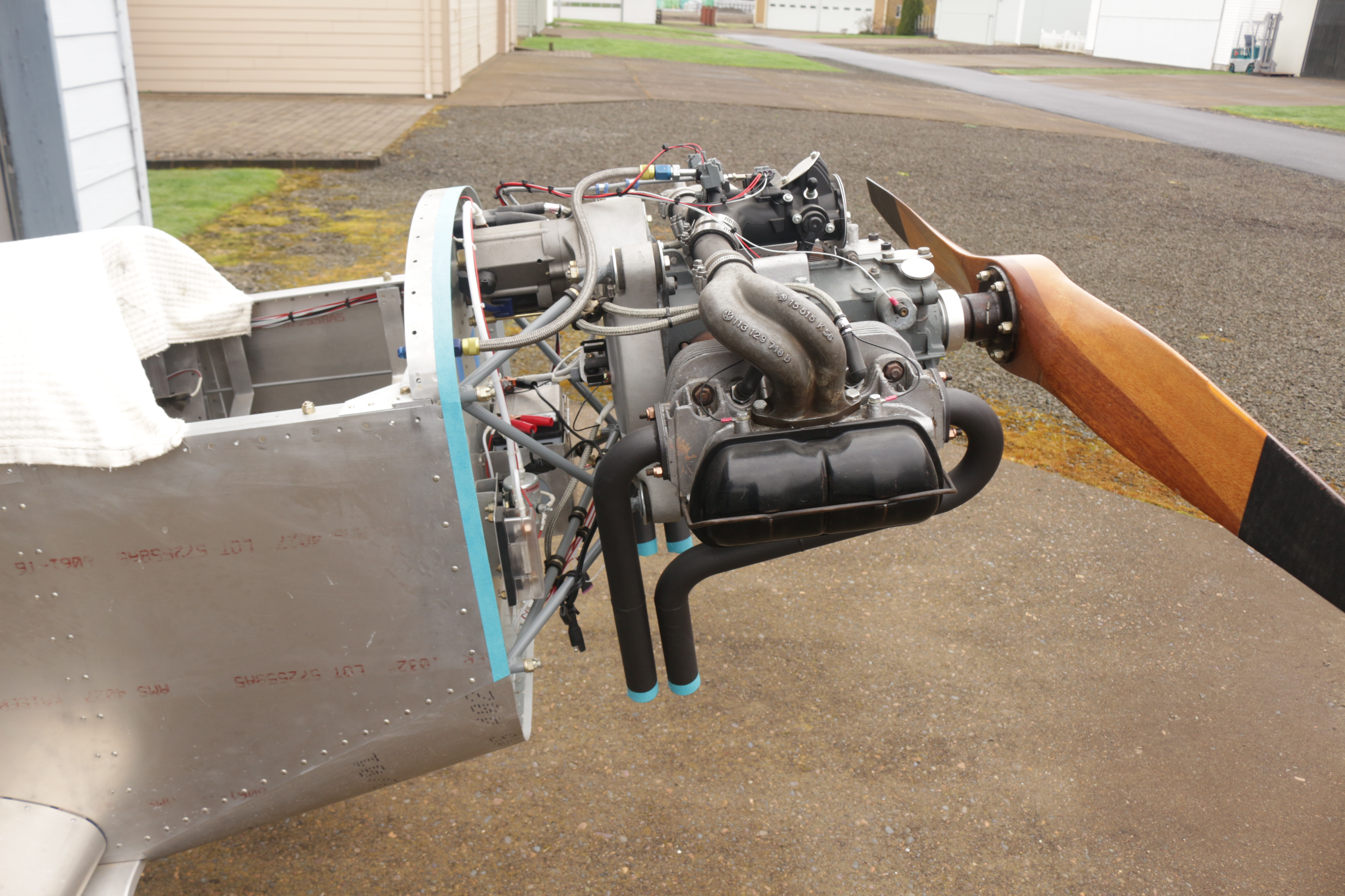
OK, so I just need to take a bunch of photos. Here is one. A picture of my engine on my Thatcher CX4 (it is the thing I have to make a cowl for):
Phone Camera
Now I got this bright idea: If I need to take a bunch of photos, why not just take a movie?! So I grabbed my high end phone and took a movie of the engine. I moved the camera all around engine like I was spray painting the whole thing. Then I busted the movie into a thousand images. Boom. Done.
I loaded the photos in Meshroom, hit Start, and waited overnight.
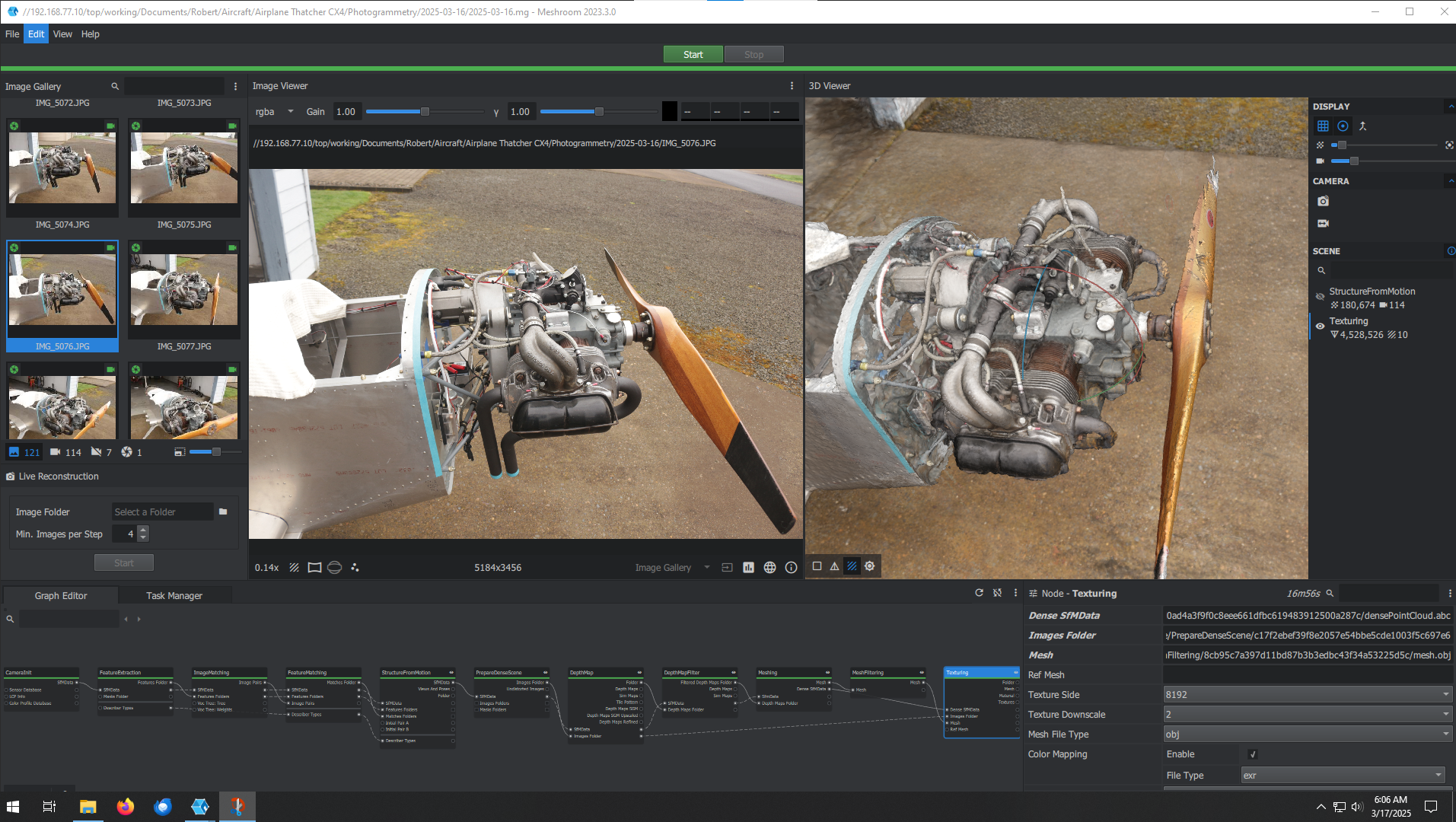
Here are a few screenshots of the software at work. This first image shows a working image in the center frame, and the point cloud in the right frame:
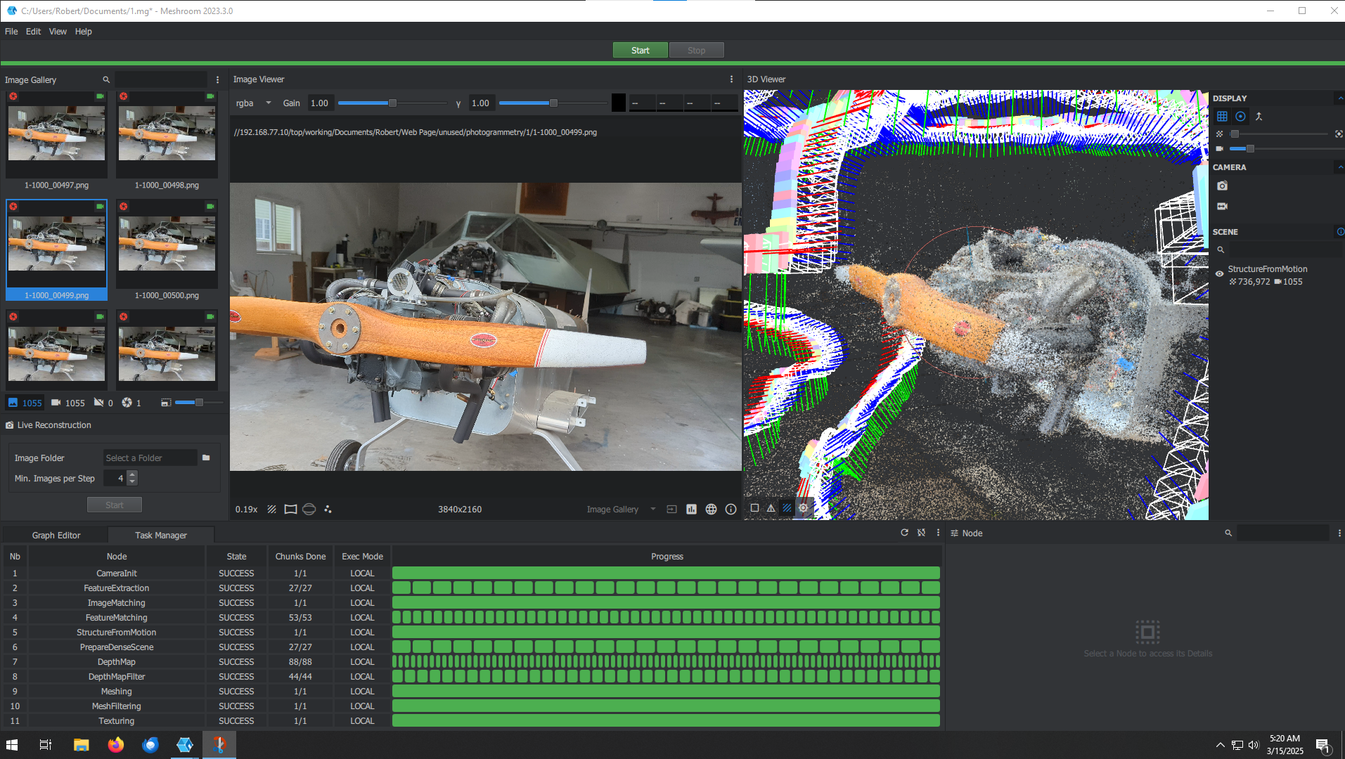
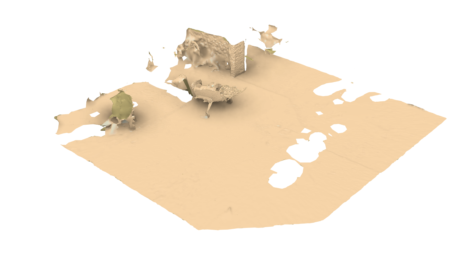
In the image below the right frame is now showing the 3D mesh. It is pretty inaccurate... like the whole thing was made with shaving cream:

OK, that kind of worked. It would have worked for my needs, but it what the heck I can do better!
Look again closely at the point cloud image. It looks fuzzy. Points are not where they should be (like dust in the wind).
My images must not be good enough, and so the photogrammetry math is not working out.
I did have the phone camera on auto white balance and auto exposure, and apparently this screws things up. Common points are selected by color, and auto white balance and auto exposure will change the color of common point from one image to another. So I set the phone camera on manual (fixed white fixed exposure) and took a few hundred new photographs.
Tried again. No good, again.
Oh wait a minute! Phone camera lenses suck. Have you ever been in a group photograph and you are on the end? You looked really wide, overweight even, but not the cool people in the middle! Phone cameras are built that way: they have this funny shape which keeps the center of the photo nice and pushes all of the distortion to the edge (great for selfies, not for group shots).
In other words, they do not have a consistent focal length. This creates errors in the math.
So do not use a phone camera for photogrammetry.
DSLR Camera
Got my right proper camera and tried again.
Point cloud looked a lot cleaner. Less random points:
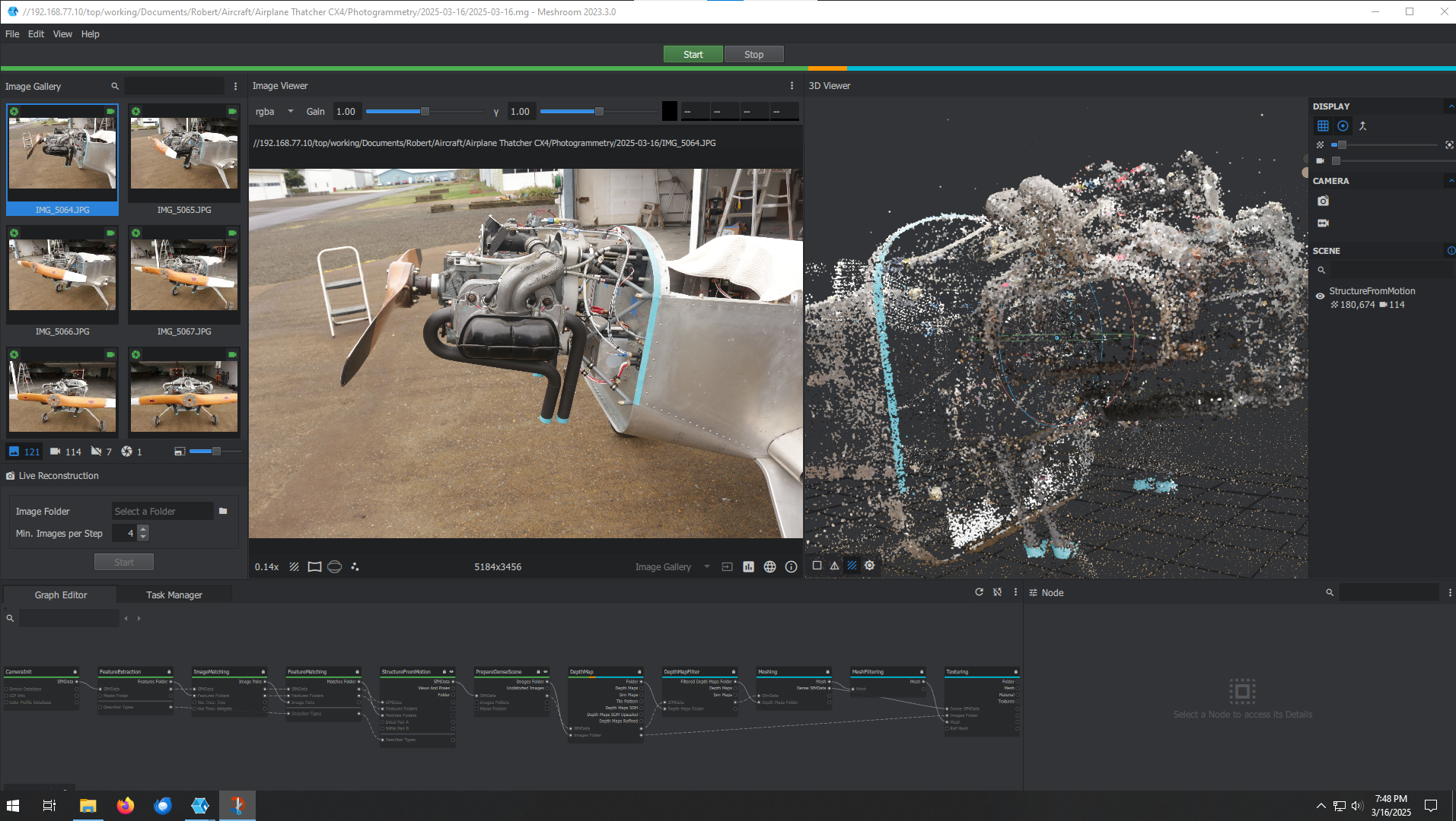
This is a screenshot of the final product. The right frame shows a 3D model (really good, right?!):
Mesh Modification
As impressed as I was with myself, I do not need a pretty 3D model of the engine. I just an accurate shape. And I need to work with a file that is not so large my computer crashes in the middle of designing.
To make the file size more manageable, I got rid of the texturing. Now it is just one color:
But I only need the front of the engine, so I started trimming the mesh:
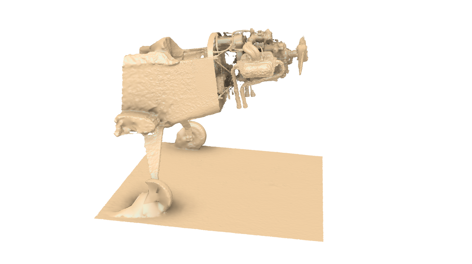
This got the file size down to something manageable (like 180 MB down from 800 MB).
3D Model of Existing Fuselage
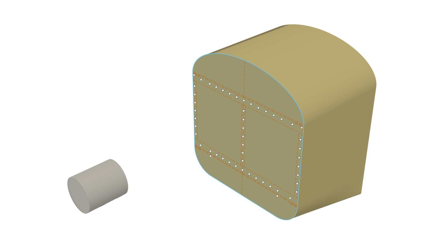
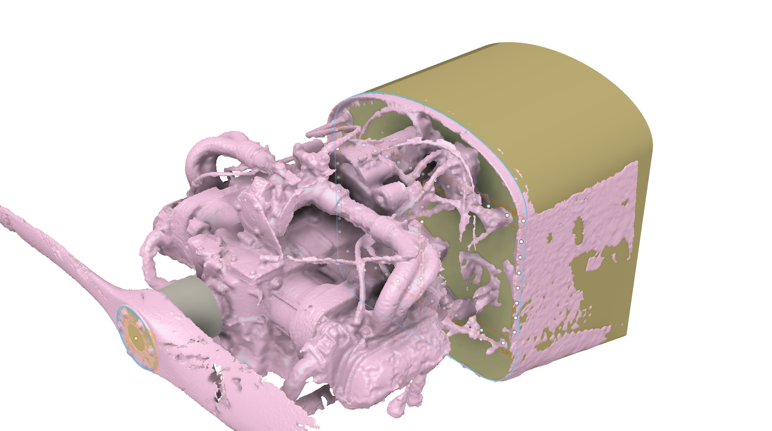
Since I already had CAD drawings of the fuselage, I was quickly able to create a 3D model using that information. I did however take field measurements of where the propeller hub was located (it is represented by the cylinder). That way I can include that into the model to ensure coordination:
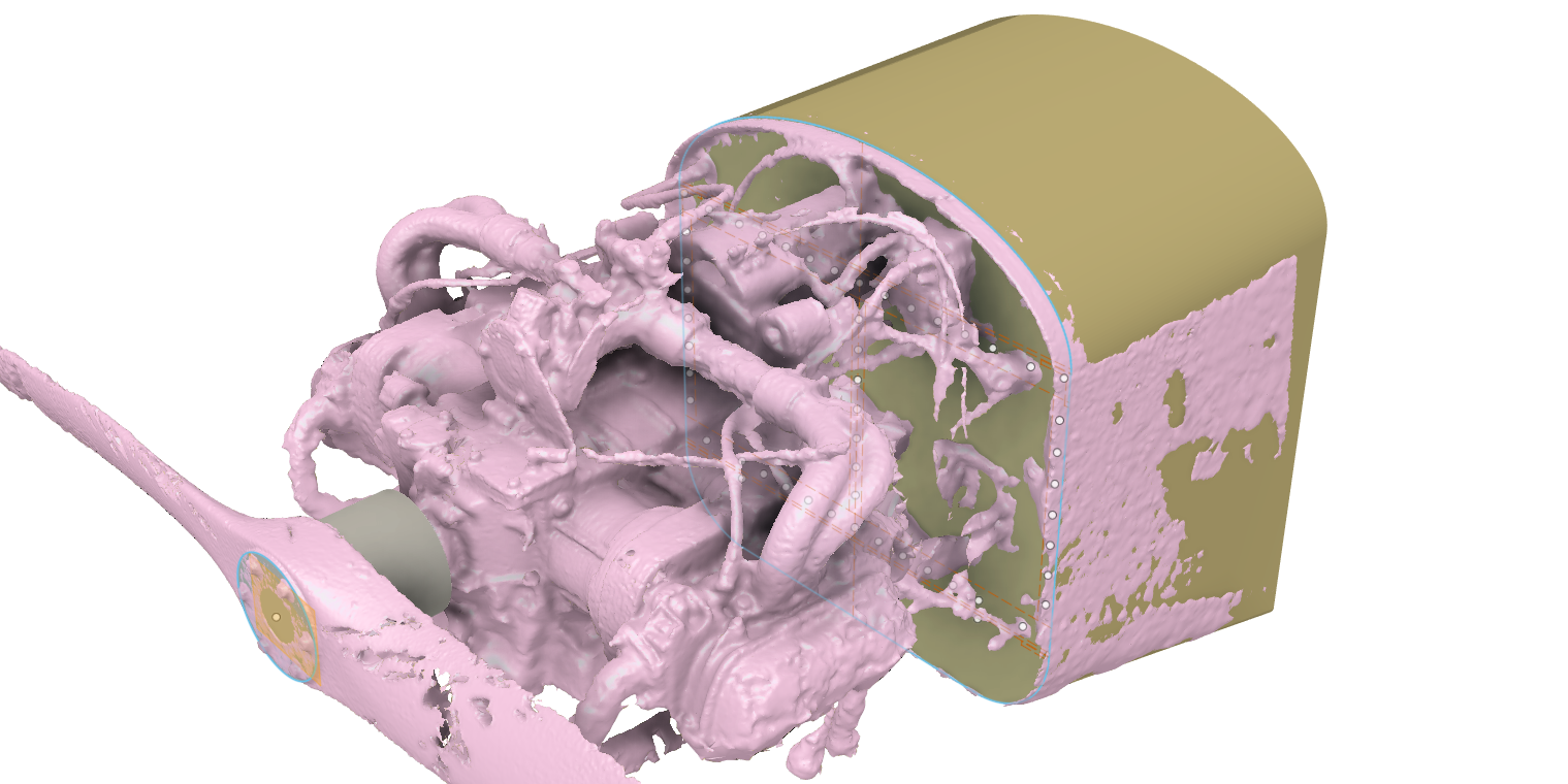
Import the Mesh into the Model
I then imported the mesh into the model:
Why pink? I do not know.
OK, this is a bit tricky so I need to write down my steps:
-
Create a component for just the mesh. It give some extra tools to manipulate the mesh (like its own coordinate system).
-
Import the mesh into this component.
-
Scale the mesh to the correct size. This I did by measuring the distance between two mesh items (for example, the left and right fuselage edges) and scaling accordingly based on that measurement.
-
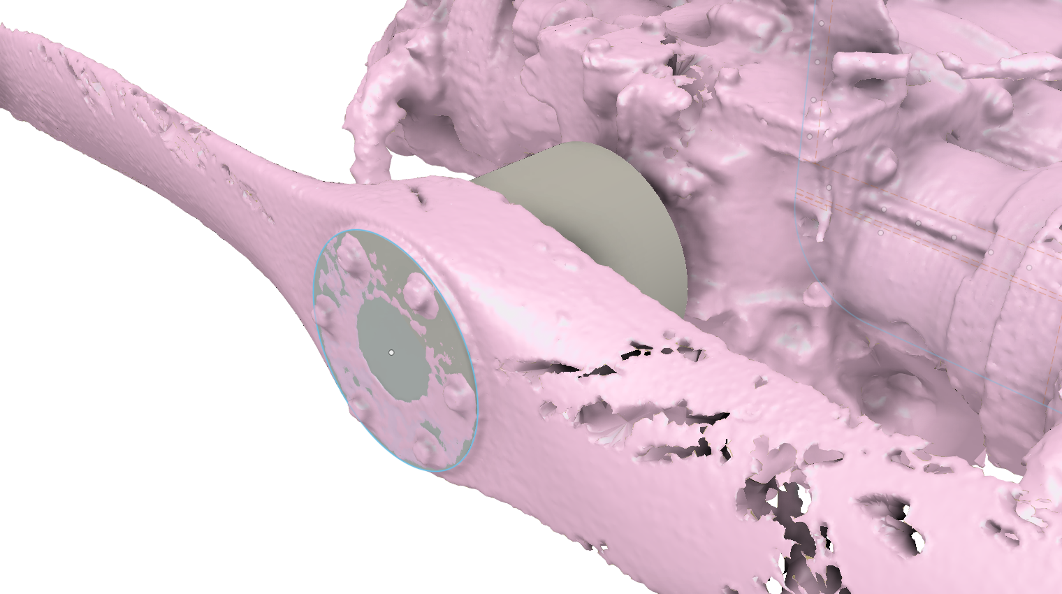
Direct Edit the mesh to create a working plane on a known surface. Here I choose the propeller hub's front surface.
-
On that working plane, create a sketch and draw something you can work with. Here I drew a circle and placed it concentric with the propeller hub.
-
Align the mesh component with a 3D entity (select Component, not Body or Mesh, when you do this). Here I aligned that circle I drew with the end surface of the 3D propeller hub body.
-
The align gets you pretty close. Then you need to use Free Move to fine tune the placement of the mesh. Here I selected the origin point of the Free Move to the center point of the hub circle. I then change rotations (by like 0.1 degrees) until the mesh's fuselage lined up with the 3D fuselage.
This looks good:
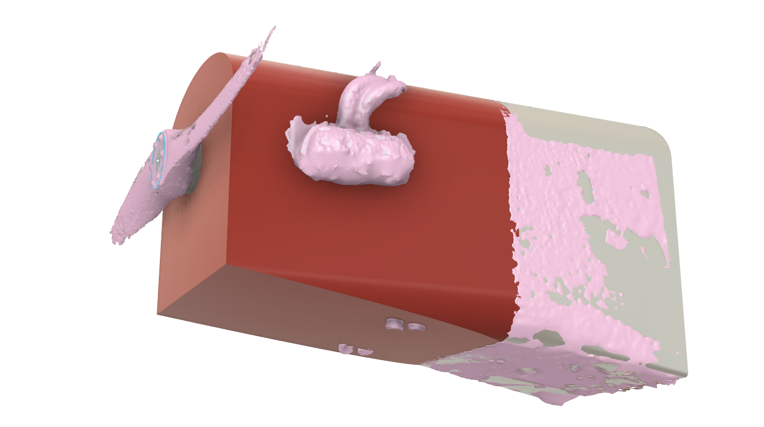
Shaping Virtual Foam
Just like the traditional method, I cover the engine with something I can shape. Let's start with a big old block. Obviously I need to shape this down, but you can also see where I need to add some virtual foam:
The following movie shows the 3D modeling steps:
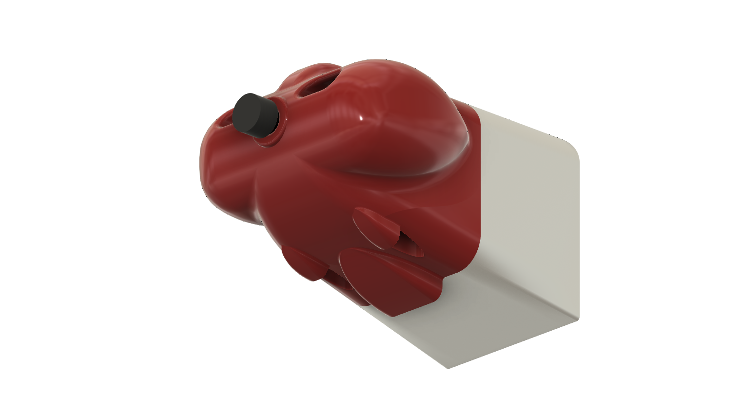
And this is the final 3D model:

It looks like a goldfish.
Cutting a Foam Mold
Before I plow through a couple of sheets of foam, I double checked to make sure the actual as-constructed firewall was the same as the virtual one. For this, I just cut a ring to wrap around the fuselage at the firewall:
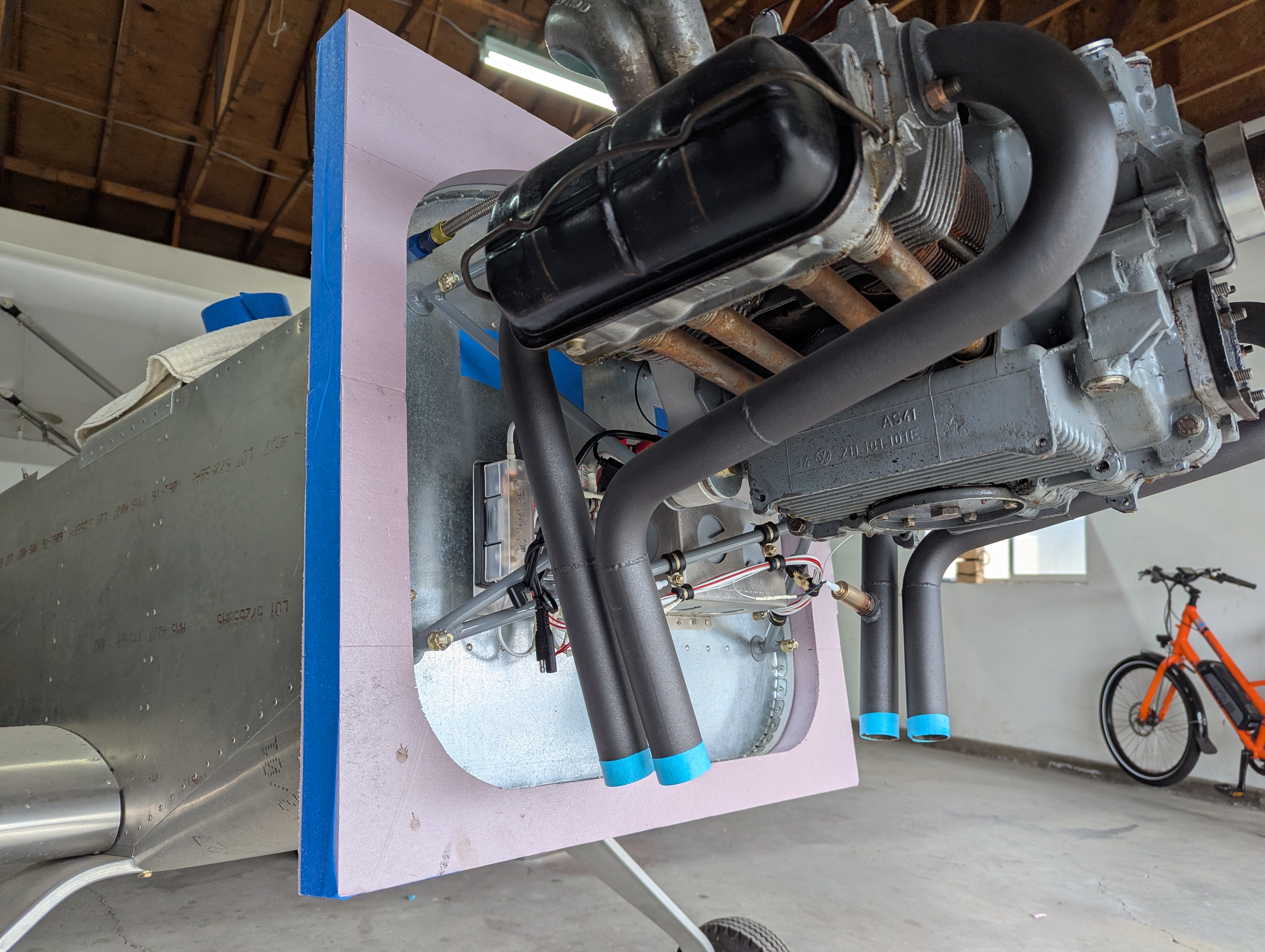
Looks good. No gaps. Double checked!
Now to double check the foam thickness. It is nominally two inches (50.8 mm). But I took five pieces, stuck them together, measured, and divided by five:
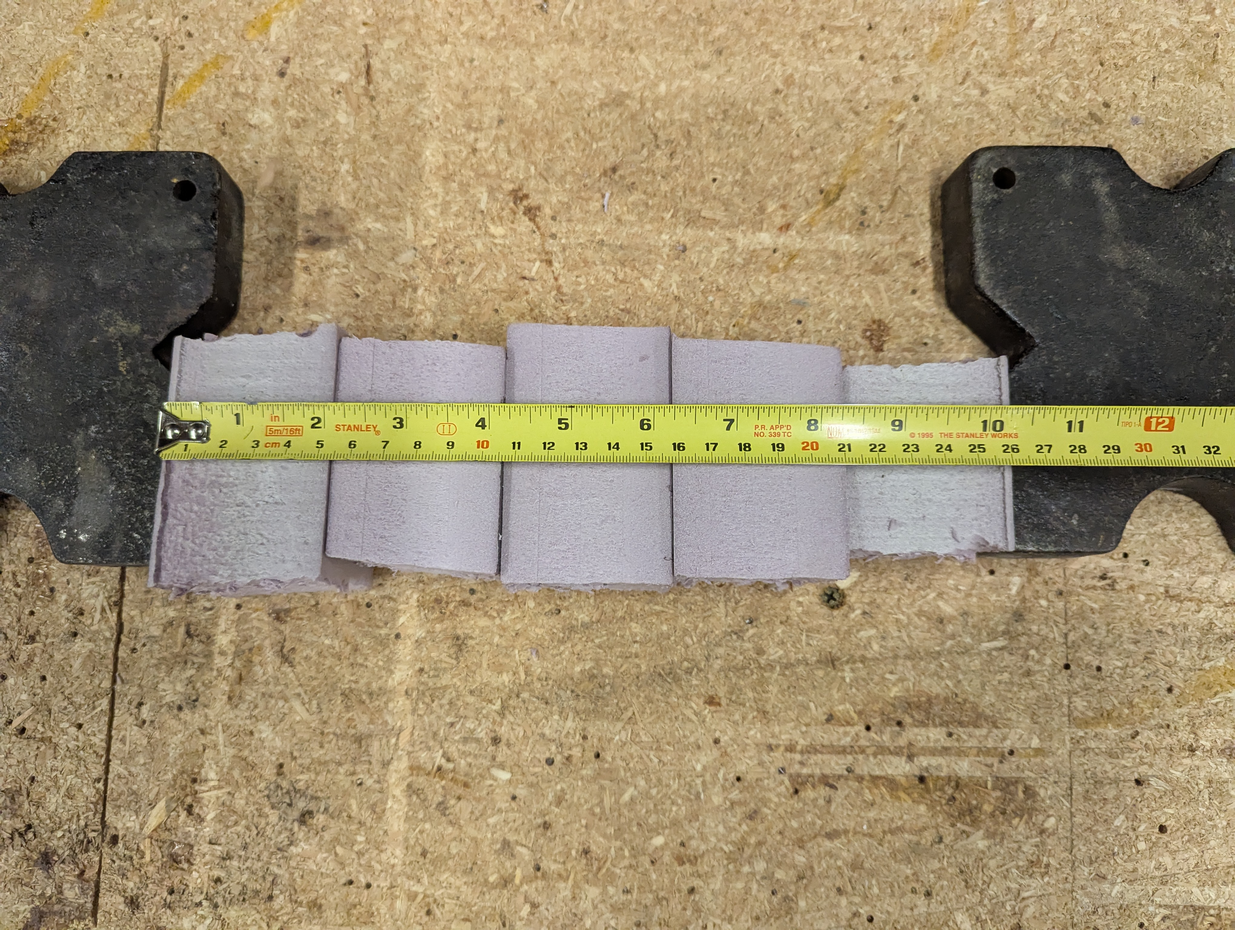
This turned out to be 263 mm, or 52.6 mm per sheet. That extra 1.8 mm difference per slice would have made the whole cowl over 20 mm too long. The cowl would have hit the propeller hub! So yes, always double check material thickness.
(UNDER CONSTRUCTION... more to come)