Designing Pre-Drilled Skins and Flanges
The following is CAD lesson on how to design wing rib flanges, bulkheads, etc. which mate to pre-drilled skins. Getting an evenly spaced line of holes in a skin is easy. Designing a curved rib, which is then bent around a form, and having its pre-drilled holes line up with the holes on the skin is a bit trickier.
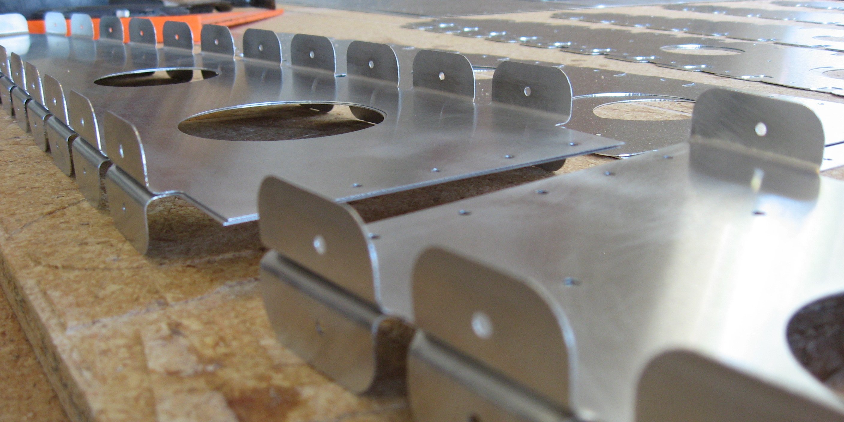
I am building an airplane out of aluminum. And I am using a CNC. When I cut parts, they are pre-drilled and ready to be Clecoed together. However...
Even if you don't predrill you skins, or if you don't plan on using a CNC, this example can show you how to layout a series of flange tab holes so that the rivet spacing on the skin is on an exact spacing, even around curves. On a finished airplane, it looks really nice to have all of your rivets evenly spaced.
Tabs as a Flange
Typically, an aluminum wing rib has a continuous flange formed along the top and bottom. If the rib was just straight (like a C-channel) it would be easy, just bend the top and bottom 90 degrees and done. The problem comes from the curved nature of a wing rib. You just can not bend the edge 90 degrees and end up with a flat part. You have two options:
-
You can bend a continuous flange, and then flatten the rib by bending folds in the flange (they are called flutes, and done with fluting pliers).
-
Or you can simple cut the flange into a bunch of tabs. This is a lot of extra work if you are doing it by hand, but not an issue with a CNC router.
Due to the organic nature of a hand fluted rib (wavy and crooked), it is not possible to pre-drill it and have the holes line up. So tabs it is!
Example
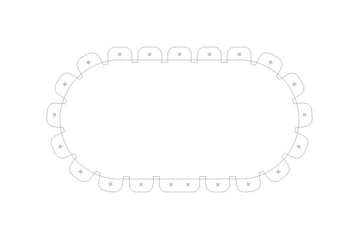
We'll start with this simple example part. Its outline is my designs datum line. For consistency, I always put the skin on the outside of this design line, and the rib has to fit inside of it.
Here is a basic example shape:
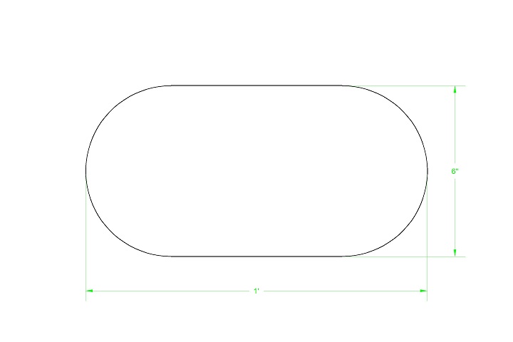
This example part will have a 3/4 inch flange that a skin is riveted to. The part will be made from 0.020 inch aluminum and will be formed around a wooden forming block. The forming block will have an 1/8 inch radius.
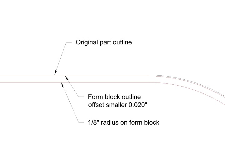
The first step is to develop the wooden forming block pattern. Since I want the finished part to fit inside of the outline, the forming block has to be smaller by the thickness of the material.
In the image below, the part outline is offset 0.020 to account for the material thickness. And to aid in part design, the 1/8 forming block radius is shown as a reference:
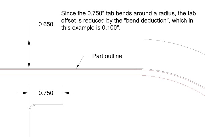
To create a 3/4 inch flange, you would initially think you should just add 3/4 inches to the part outline. However, this does not take into account the fact that the flange is bent around a curve. This shortens the distance the material has to go to get to the end of the flange. This bending also stretches the material a little, and this must be accounted for. The reduction in the flat pattern due to these two items is called Bend Deduction.
Go ahead and do an internet search on Bend Deduction. You will find formulas on how to calculate it. My method: Just form something and measure the result. As an example, I took a 2.000 inch strip of 0.020 inch aluminum and bent it 90 degrees around a block with a 1/8 inch radius. You would think that I had two 1.000 inch sides. However, each side was 1.050 inches, or 2.100 total. So I now know that 0.100 inches is added, and so it must be subtracted from the original design.
To create a 3/4 inch flange we will be adding only 0.650 to account for the Bend Deduction (0.750 - 0.100):
I want a rivet spacing of 1-1/2 inch with the rivet in the middle of the 3/4 inch flange. Importantly, offset the hole from the outside edge of the flange:
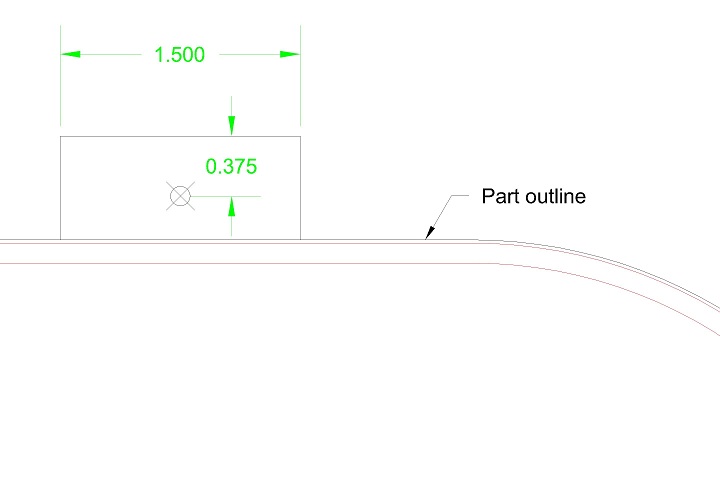
Since I plan to use a 1/4 inch diameter router bit to cut out this part, I need to decrease the tab width a little more than the width of the bit to allow it to get in between the tabs.
Next, create an array in CAD that generates all of the tabs. Most CAD programs have the ability to create an array around a complex path. This is key since this will provide an exact spacing around my curved part.
I want my tabs to cut down past the the beginning of the form block radius, so I have extended the tab edges down to that line (otherwise you get these weird little humps in that area). I just have the two side of the tab and the hole at this point; I will draw in the tops and bottoms in a second:
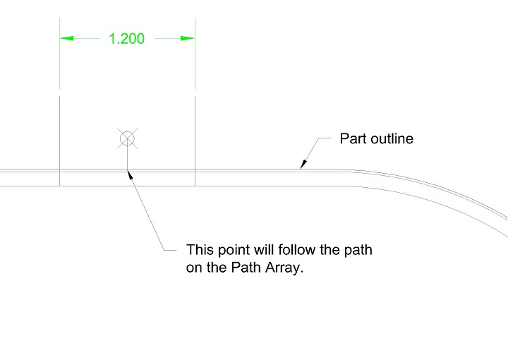
I create the array, setting it to space my items to 1.500 inch exactly and follow the part outline.
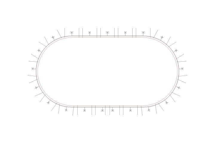
You can see in the image below that the tabs appear to be inexact at the curves. If you measured the distance between the points, you'll find that it's greater than 1.500... but once the tabs are bent around the form, the holes will be in the proper location.
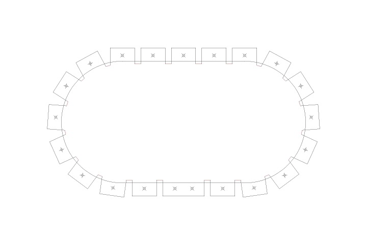
To clean up the tabs, I extend all of the lines to the 1/8 inch radius line again (you can see where they do not touch where bent around the curves), and then connect all of the top and bottoms as shown below.
On this particular part, the skin will connect at the bottom... and I have provided a tab with two holes to provide a location to butt the skin edges together.
As a matter of preference, I like to radius the tab edges.
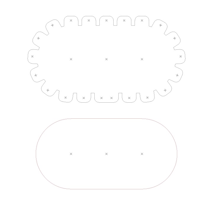
I then put in some tooling holes (so the material and the form blocks can be lined up when pressed together) and that is it! The part and the form block designs are shown below. I can then cut these on the CNC, or print this on paper and glue that to the aluminum and wood to cut it all out by hand.
The result of all of this work is the skin can be drilled with a line of holes spaced exactly at 1.500 inch (which is pretty). It can then be wrapped around this part and all of the holes will line up (which is awesome). You also have the benefit of knowing that the assembly is correct if the holes line up. If the holes don't line up, then something is wrong.
I hope this helps. Keep building!