CNC Rail Grinding Jig
When building a CNC, one of the common linear guides are V-groove bearings riding on a simple track. This track is normally a flat plate or common extrusion with the edge ground to match the V-groove bearing. One could buy this track (expensive), fabricate this track using a hand file (laborious), or fabricate this track using a mill (complicated). I have found it easier to simply use an angle grinder (which is fast) but this requires a jig to make it accurate.
The following are the instructions and plans to make a grinder jig to hold a angle grinder to fabricate CNC linear rails.
Grinding Rails
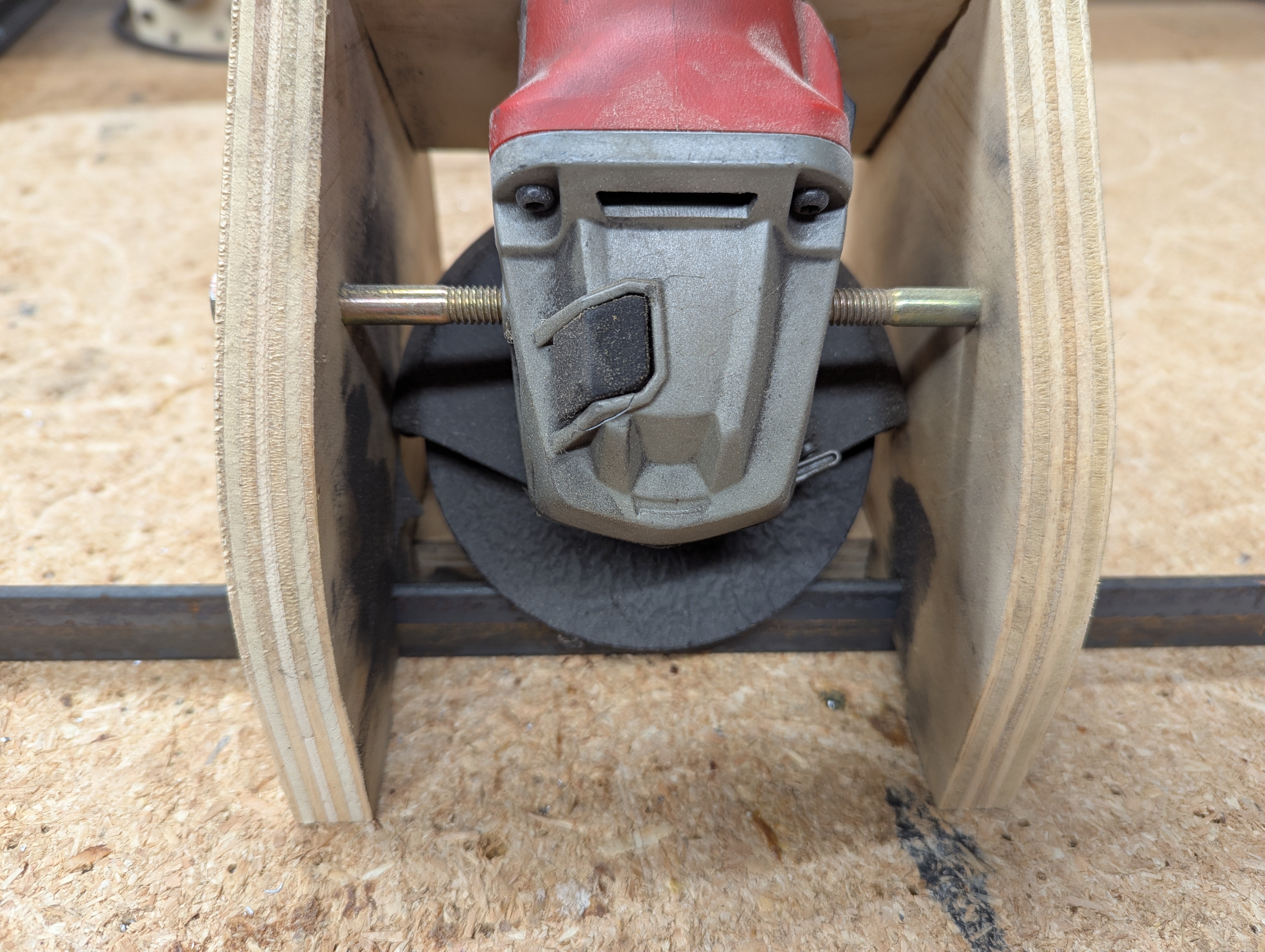
On my last couple of CNC routers, I used V-groove bearings to ride along a steel track that I fabricated. This steel track was made from a 1 x 1 x 3/16 inch steel angle. I fabricated a wooden box of a jig that held the grinder at the correct height and correct angle with respect to the steel angle. For the V-groove bearings, this angle is 45 degrees on each side.
You then place the steel angle on the table, the jig over the top of that, and work the grinder by hand.
Building the Jig
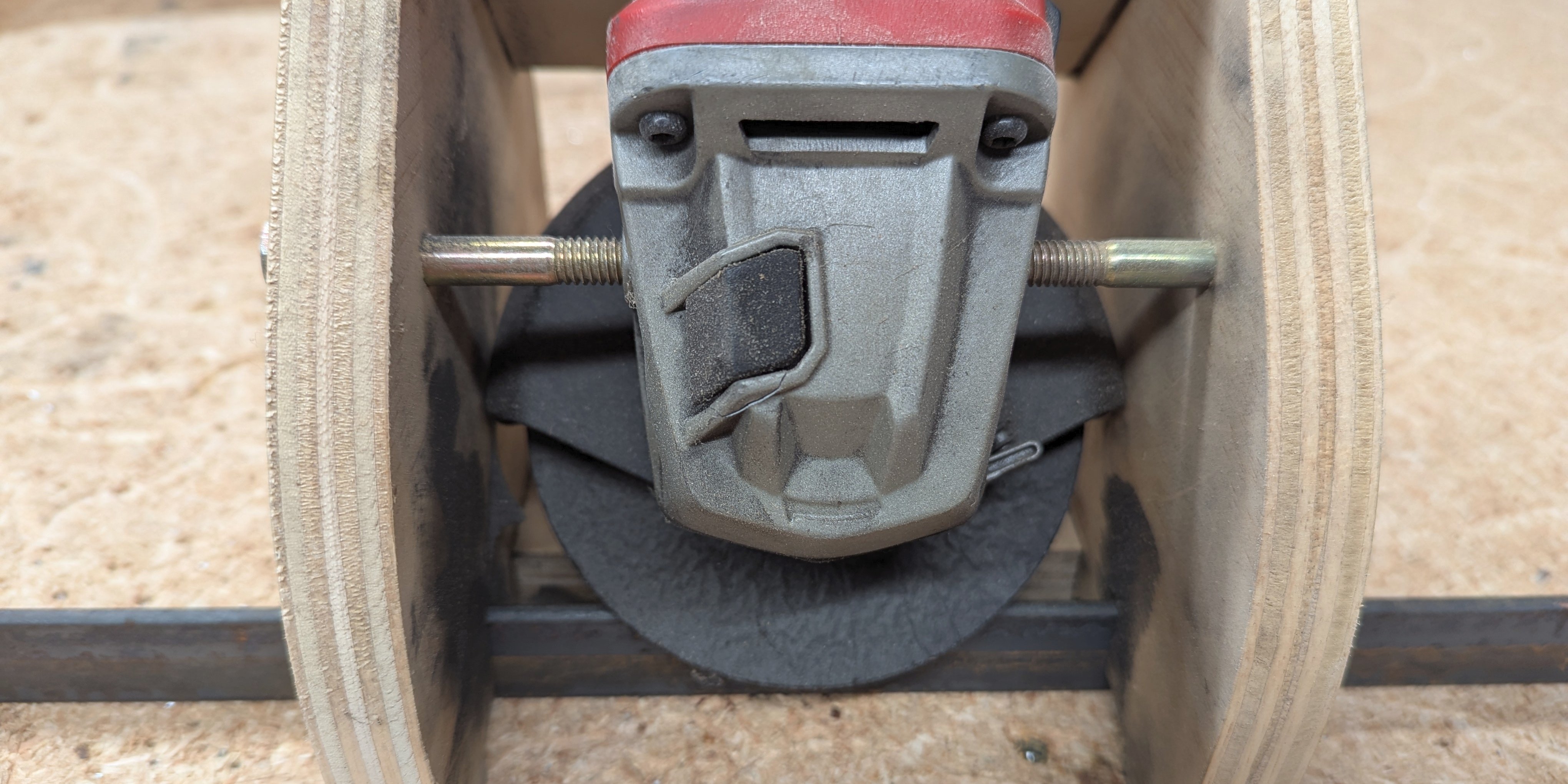
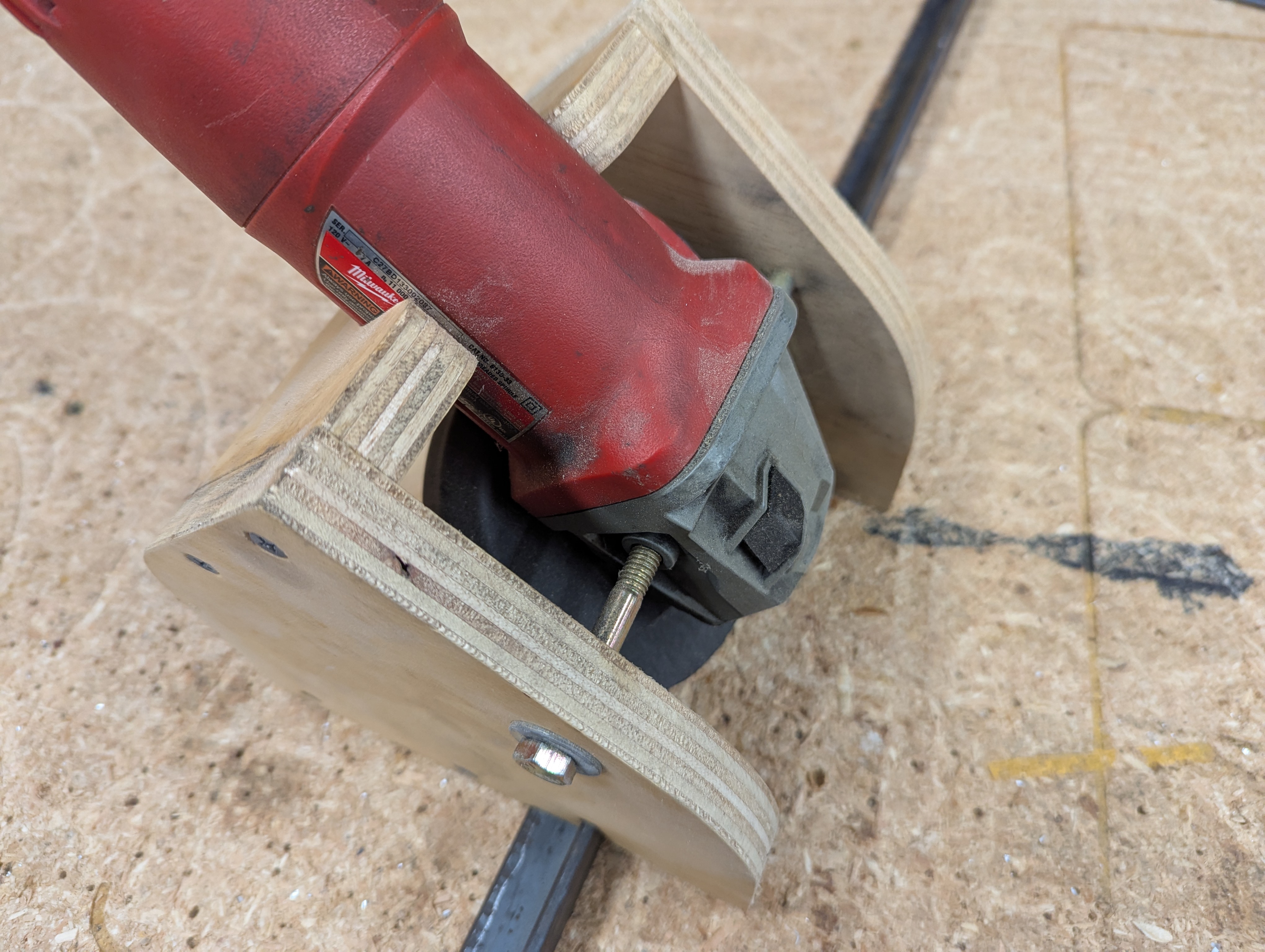
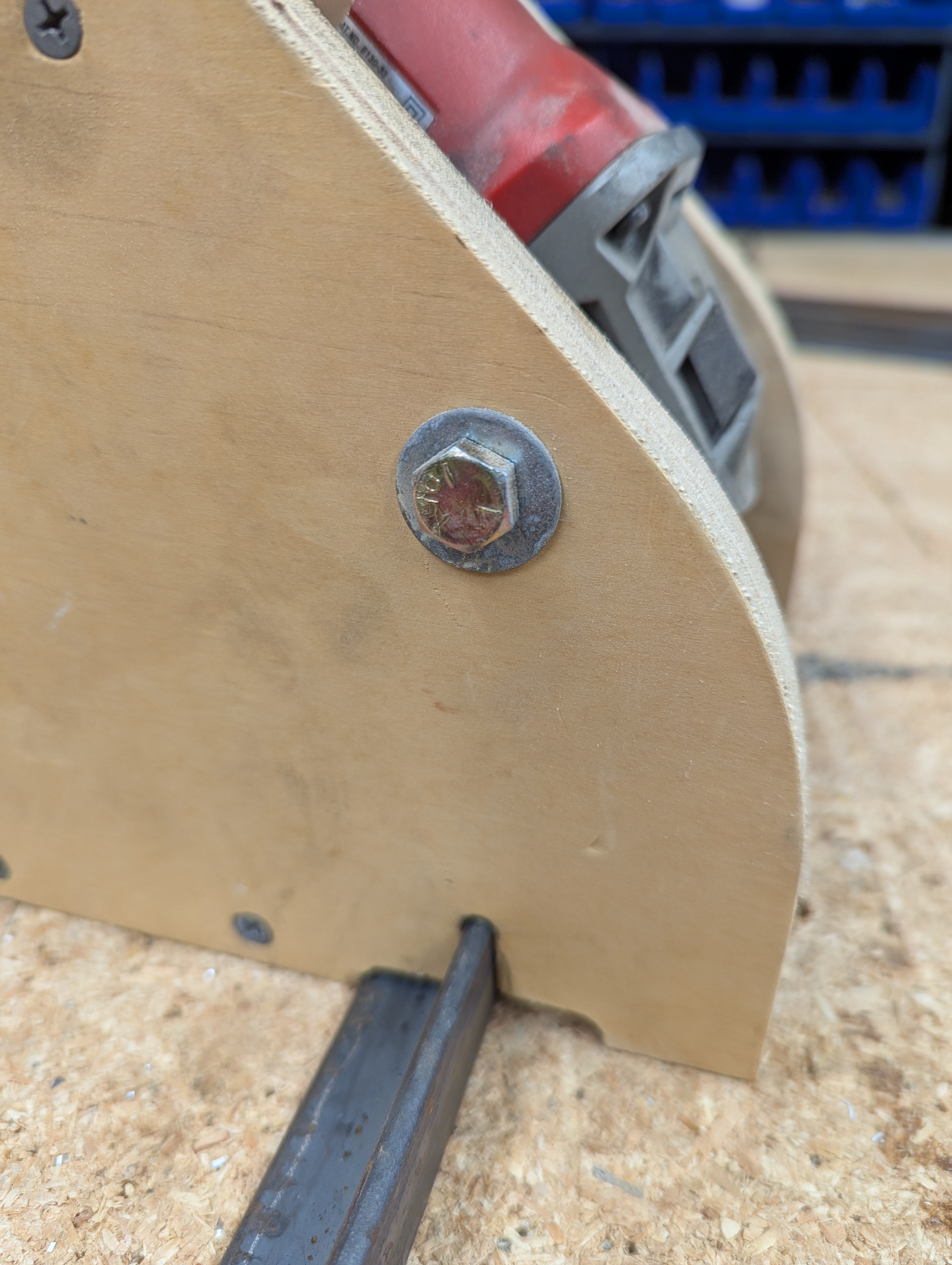
This jig works for the Milwaukee 6130-33. It is the one I already had. It has two threaded holes on each side for a handle (like most angle grinders), and these are used to bolt the grinder in the jig. This jig also works with the grinding wheel that I have. I had to actually make a prototype or two before I got everything lined up. In other words, this is a starting point for you; be prepared to make changes.
The jig is made from 18 mm plywood, although 3/4 inch or 19 mm plywood will work fine. The CAD file for the plywood parts is here: Rail Grinding Jig CAD File.
You should get a CAD file that looks like this:
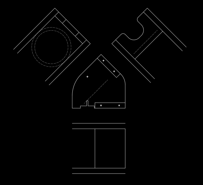
The top image is the three-view sketch of the assembly. The lower image is the cutting layout used to create GCode files for the parts. More details about creating GCode files in this fashion can be found here: DXFtoGCode - Free CAM Software from WorktableCNC.
If you do not have access to a CNC... well that is terrible. You will have to:
-
Take that CAD file and print it on paper to scale.
-
Using spray adhesive (3M Super 77 or similar) lightly glue the paper to plywood.
-
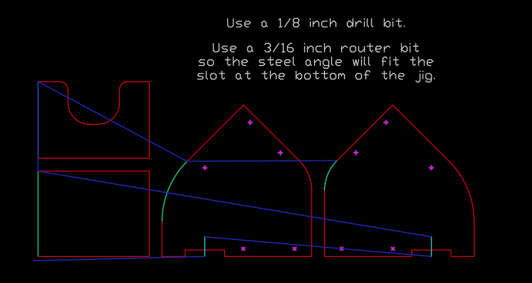
Using the printed lines as a guide, drill the holes and cut out the parts.
If you do have access to a CNC:
- Watch the CNC drill the holes and cut out the parts.
Then, assemble the jig.
Done!