DXFtoGCode - Free CAM Software from WorktableCNC
Introduction
Computer Aided Manufacturing (CAM) Software does not have to be complicated. This page provides the instructions for using DXFtoGCode, a simple and free program to convert a DXF file into GCode files.
CAM software is generally not hard to find. What sets DXFtoGCode apart is how the operator defines the non-milling operations: things like the order in which to cut out parts, where the starting point is, how and when to change tools. For simple 2D CNC work this should not be complex. However, in most feature-rich 3D CAM packages the features become burdensome.
DXFtoGCode has a focus toward 2D flat panel work. For 2D work such as cutting plywood or similar sheet stock, using simple 2D drafting CAD (AutoCAD LT, LibreCAD, etc.) and DXFtoGCode is quick and easy.
If you truly need 3D milling or 3D printing of complex shapes then you should use a 3D parametric solid modeling CAD with integrated CAM (Fusion 360, FreeCAD, SoldWorks, etc.). Some designers try to use only one CAD package for everything, and typically this single tools is 3D parametric CAD. However, designing flat panel layouts in 3D software is a ridiculous amount of extra work.
My suggestion:
-
Use 3D parametric CAD for 3D milling or 3D printing ('cause you have to).
-
Use 2D CAD and DXFtoGCode for flat stuff ('cause it is way faster).
Why is it Faster?
Anytime you have a bunch of flat parts to draw, regardless of what CAD you use you have to make a 2D sketch first. So just stop there. Then just arrange those parts as you would want them cut from some material (this is called nesting).
To make a cutting file from that arrangement, logically the CAM software needs to know:
-
Which is an outside path (a part) and which is an inside path (a hole). This little detail places the tooling offset on the correct side and establishes the direction of cut (conventional or climbing).
-
The order in which to cut paths. Obviously, you can not cut parts free before you cut their interior holes.
-
The start point of every part. For example, if your part is on the edge of a sheet, you want to cut the free edge first and THEN cut the part free from the sheet.
In most other 2D CAM software, these steps are automated. It is great when it works. But often you do not get exactly what you need. You end up manually adding a bunch of workarounds for force it to give you what you want.
So as opposed to fighting automation with workarounds, just skip that step.
In DXFtoGCode the non-cutting CNC movements are defined in the DXF file. You draw how you would like the CNC to move between cuts, where to start, and which way to initially go on a path. It is simple, and developing cutting files is quick. This is the advantage of using DXFtoGCode.
Download
DXFtoGCode is free, written in Python, and a zip file can be downloaded here:
After you download the zip file, extract it to your working directory (Home, Documents, whatever).
This Python program requires that you have Python3 installed. Download it for Windows or Mac, it comes standard on Linux.
For Linux, change the permissions of DXFtoGCode.py to executable (Run as a Program or chmod +x).
If it does not immediately work on Windows by double clicking on DXFtoGCode.py, it usually a Python/Windows permission or a Windows PATH problem. Often it works under Python's IDLE or even from Windows CMD command prompt, but not initially from File Explorer. It is a Windows problem, please check the internet for a solution...
My solution was based on how Python was installed on Windows. Going to the Python website and downloading and then installing it created an app which floated on top of Windows (for lack of better words). This way did not work. Opening a terminal (press Windows key and then type cmd) and then typing python3 opened a Windows App Store window. Just install it from there. Now Python is installed inside of Windows (again, for lack of better words).
Getting Started
The first requirement is that you have to be able to save your drawing file in AutoCAD Release 12 DXF ASCII. This is an open drawing standard text file (which makes reading it with Python easy) and regardless of which CAD program you use this file type is usually an option.
This software creates GCode files which use cutter compensation G40, G41, and G42, it creates subprograms with O100, and uses variables with #<...>. These codes can be interpreted by LinuxCNC controllers (PC based), but it is beyond the capabilities of GBRL controllers (microcontroller based).
The following are the basic rules for creating a workable CAD/CAM drawings file for DXFtoGCode:
General
-
You create a drawing of the nested parts as they will be cut on the CNC. Nest them with appropriate space to allow for tooling.
-
You will use specific layers to indicate movements like drilling (G81), milling (G1, G2, G3), and rapid moves (G0). This is detailed below.
-
Any set of connected lines or arcs will be milled as a continuous path (the Z axis stays down).
-
Always Snap-On-Endpoints where lines and arcs connect. If lines and arcs are to be connected into a path, then the start of one should be exactly the end of the previous. If you can zoom in and the ends are not touching, the CAM software will not see it as connected. When using CAD, turn Snap-On-Endpoints on.
-
You obviously can use polylines, blocks, splines, ellipses, and other complex shapes when developing the drawings, but all of that needs to be exploded down to simple lines and arcs.
Drilling
-
Drawing points define where to drill.
-
Any point on a layer that stars with
DRILLwill generate a drill cycle. -
If different
DRILLlayers are created, such asDRILL-3,DRILL-6,DRILL-0125, etc., then a separate GCode drill file will be created for each layer. This facilitates single tool changes. -
Points may be placed in three dimensions. The Z axis value determines the final depth of the hole.
Not all CAD software is three dimensional. Some only provide a DXF file with X and Y; Z is not provided. In this case place the holes not drilled down to Z=0 on a separate DRILL layer. Then you manually modify that separate GCode drill file using a text editor.
Milling
Paths are placed on three primary milling layers: MILL, DADO, and ENGRAVE. Use only lines and arcs; no poly-lines, splines, ellipses, or blocks.
-
MILL: This defines full depth cuts. The paths can be placed in three dimensions, but normally Z=0 (or no Z information) provides a cut down to the spoil board. The Mill feed rate and spindle speed in the setups file will be used. -
DADO: This provides aMILLtype cut at a preset Z height. This allows those using CAD systems without a Z axis to create dado cuts at a height other than Z=0. The dado depth is defined in the setups file. The Mill feed rate and spindle speed in the setups file will be used. -
ENGRAVE: This defines engraving cuts (or a nice place to put text when using a pen holder). Similar to dado cuts, this creates cuts at a preset Z height. The Engrave depth, feed rate, and spindle speeds is defined in the setups file.
Circles
Circles are special:
-
Any unbroken full circle (not a collection of arcs) placed on the
MILLlayer will create a helix cut in the mill file. This helix cut is offset with cutter compensation (the circle represents the edge of the hole, not the tool path). This is used to bore accurate holes using the router or milling bit. -
Any full circle placed on the
DRILLlayer will create a drill cycle in the drill file AND a helix cut in the mill file as noted above. This extra drill cycle is used prior to this helix cut as a rough material removal (it makes the helix cut a little easier on the CNC).
In the above two cased, the circle can be placed in three dimensions. The Z axis value determines the final depth of the operation.
-
Any full circle placed on the
DADOlayer will get milled normally with tool compensation (the circle represents the edge of the hole, not the tool path). This is great for a fastener counterbore. -
Any full circle placed on the
ENGRAVElayer will simply be engraved normally (the circle represents the tool path). -
If you actually need a circular part cut with normally milling, you have to split it into two arcs (paths are defined by lines and arcs). And now this gives you endpoints to work with. You can then place one of the arcs on the
FIRST,FIRSTLEFT, orFIRSTRIGHTlayer and connect aRAPIDline to it (see below for these details).
Rapid Moves, Starting Points, and Cutter Compensation
If you wanted to do a bunch of engraving, then what you have read thus far is all you need. Engraving simply engraves down the center of the path, requires no tooling offset, and paths can be cut in any order. This also applies to slots. A slot is a cut with no offset or order either on the MILL or DADO layers (typically used when you need an assembly slot or dado, when the tool and the material is the same width, and one quick line will do).
For cuts which are not engraving or slots, you generally need to know the offset side and direction. And often you need to specify the order in which to cut out the parts.
This is where the layers RAPID, START, STARTLEFT, and STARTRIGHT are used.
-
RAPIDis used for rapid movements. -
STARTdefines the start point of a path. -
STARTLEFTis similar toSTARTbut enables cutter compensation to the left (G41). -
STARTRIGHTis similar toSTARTbut enables cutter compensation to the right (G42).
Starting Points
If you have an open path (where the two ends are at different locations):
-
Change one of the end entities to the
STARTlayer, then it starts there and will follow the center line of the path. -
Or use
STARTLEFTorSTARTRIGHTand cutting compensation to that side will be enabled.
No further information is needed for an open path, since the START entity also has an open end and the software knows to start at that endpoint. But it will cut all of these paths in no particular order.
Cutting Order
For situations where the order in which things get cut is important, the RAPID layer is used. This is done as follows:
-
Place a line on the
RAPIDlayer, starting at the origin (0, 0, 0), and ending on beginning of theSTARTentity of your first path. When usingRAPIDyour paths must start with one of theSTARTlayers. -
Connect the next and remaining paths with more
RAPIDlines. Where one path ends place aRAPIDline where the next path starts. This will create a cutting order.
That first RAPID line with its end at the origin only gives the software a logical starting point. The CNC will not actually move and start from there. It will move from wherever it currently is to the first milling endpoint.
Closed Paths
Typically you will be making parts and those have closed paths; there is no beginning or end, it is just a closed loop. A closed path can either be a path:
-
Without any
STARTentity and not connected to aRAPIDline. This is typical for engraving, bad practice for anything else. The software will simply start anywhere on the path and go in either direction all the way around. -
With a
STARTentity and connected to aRAPIDline. Yes, it must have both. On a closed path, once you define aSTARTentity you must also define which end of that entity to start on.
Confused Yet?
The above seems like a lot. In the download there is a DXF drawing file named combinations.dxf. Yep, it shows all of the above in their acceptable combinations.
Putting it All Together
So you draw a bunch of lines, arc, and points on several different layers. Save this to a DXF Release 12 ASCII (text based) file. Run the Python script DXFtoGCode.py, input the file name and desired setup, and you should get GCode files. These files may include:
-
example-drill: Drill cycles from the points on theDRILLlayer. -
example-drill-whatever: Drill cycles from the points on theDRILL-whateverlayer. -
example-drill-circle: Drill cycles from the circles on theDRILLlayer. -
example-engrave: Milling paths on theENGRAVElayer. -
example-mill: Everything else.
The file example-mill will provide all of the other operations in the following order:
-
The circles on the
MILLandDRILLare bored (a helix mill cycle). -
The entities on the
DADOlayer are milled. -
The unordered entities on the
MILLlayer are milled (these should be slots). -
The ordered entities on the
MILLlayer are milled (these should be parts).
These are separated into files since it is expected that a tool change will be necessary. This way, you set a tool and then run its associated file.
An Example
Elsewhere on this site is the page for the CNC Rail Grinding Jig. It is used to grind the edge of a steel angle to allow a V-groove bearing to ride along it. The details are here: CNC Rail Grinding Jig. And the CAD file for it is here: Rail Grinding Jig CAD File. We will use this as an example. Check out that page and open the drawing file, it will help make sense of the following.
If you were drawing this from scratch, the first step is to simply draft the views of the assembly:
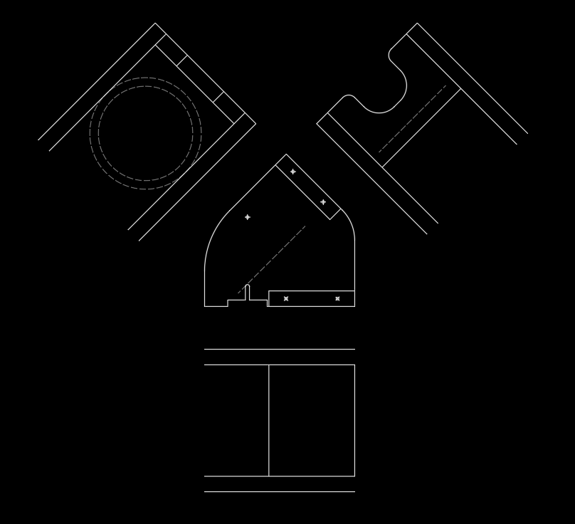
As you can see above, the side view is surrounded by the two top views and the bottom view. That side view was drawn first, then the other views were projected using traditional drafting methods.
This is obviously drawn to exact scale, but you will notice that nothing is dimensioned and not every line is drawn. It is a sketch, and that is all we need. Quick and easy!
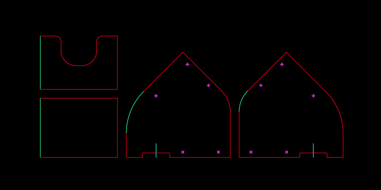
The individual parts were then drawn by using copy-paste from the assembly and then cleaning up the unnecessary lines. Below you can see the two sides, the top, and the bottom. These were also arranged how they were to be cut on the CNC (this is called nesting). They are all now on the MILL layer (shown as red) and the points are on the DRILL layer (shown in violet):
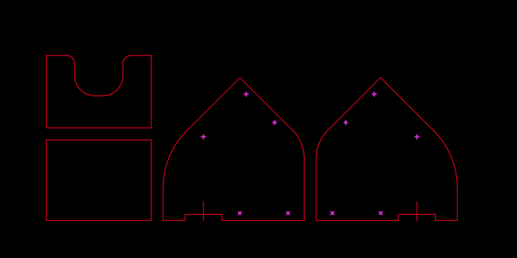
When nesting the parts, I have a good idea of the order that the parts are going to get cut and which side I am going to cut first. In this arrangement, the parts will be cut from the lower left corner of a piece of plywood. And, this plywood will be screwed down to the CNC table, but the parts will not (they will come free once cut). This means that you can not cut the parts to the right first; the remaining material for the parts on the left will then not be held into place.
So, the order will be the lower left part, the upper left part, the middle part, and the right part. Basically working from left to right always paying attention to what remaining material is available.
Moving on...
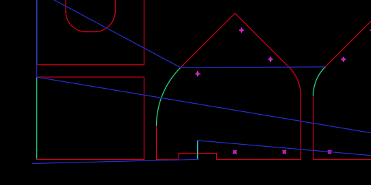
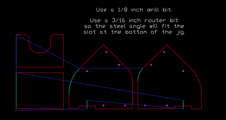
Below I have changed certain lines from the MILL layer to the FIRSTRIGHT layers (shown as light green). This indicates where I want to start cutting, and it will turn on Right Cutter Compensation (G42) for those paths.
Two special cuts are the slots at the bottom of the two sides. Because I just want the CNC to follow the exact path of those lines, those are on the FIRST layer; no cutter compensation is necessary.
Then I tie the whole thing together with a series of lines on the RAPID layer (shown as dark blue). Starting at the origin (0,0) a line is drawn to the endpoint of the FIRSTRIGHT line on the first part (the milling program starts there!). At the end of that path (which because it is a closed path is the same as the starting point) we connect a line to the beginning of the next part.
Well, normally that is how it is done, but in this case we are starting with the two slots. So you can see the dark blue RAPID line starting at the origin (bottom left on the drawing) and ending at the first slot. Then a RAPID line is drawn from the end of that slot to the next slot. And then the series of RAPID lines connect the remaining parts as described above:
At this point the drawing is saved as an AutoCAD R12 file in the working directory of DXFtoGCode, and our awesome Python script is run. Seriously, this takes seconds. I will type that again: you spend seconds working with this CAM software start to finish.
This will produce two GCode files: one for drilling and one for milling.
Done!
JSON Files Explained
In the subdirectory support are all of the setting files and working Python files. You will need to modify the JSON setting files as necessary for your tooling, setups, and other preferences. JSON files are text files, so any text editor will open them.
Hint: Please be careful of the syntax (the commas, the brackets, etc.) because one wrong comma or bracket will keep the whole thing from working. And please note that there are commas between all listed items (even bracketed groups) and the last item in list does not have a comma after it (I screw this one up all of the time).
DXFtoGCodeInfo.json
This JSON file stores general settings.
-
DefaultPathIn: The full path to the input file directory. -
DefaultPathOut: The full path to the output file directory. -
DefaultFile: The default input/output file name. -
DefaultExtension: The file extension for GCode files. -
DefaultExtensionGBRL: The file extension for GBRL files. -
SearchAccuracy: How close two endpoints need to be to be considered connected.
CAD software usually uses a whole lot of decimal places, but this program can not assume two numbers are identical. For example: an endpoint at (1.000000, 5.000000) is not mathematically the same as (1.000001, 4.999999) so is this equal to? will not work. In response the program checks two endpoints with are they within SearchAccuracy?. Additionally, some drafters can not connect endpoints (a rookie mistake) and this setting will allow them to get away with it.
I suggest something only as small as it needs to be (not 0.00000001). I use 0.1 when if I use Metric and 0.001 for US Customary (I never design two endpoints within 0.1 mm or 0.001 inch that are not connected).
Header: This is a list of text which gets added to each GCode file.
Here is an example of my general settings file:
[
    {
        "DefaultPathIn": "//192.168.1.10/samba/working/Documents/Robert/CNC",
        "DefaultPathOut": "//192.168.1.10/samba/shared/cnc",
        "DefaultFile": "example",
        "DefaultExtension": "ngc",
        "DefaultExtensionGBRL": "gcode",
        "SearchAccuracy": "0.1",
        "Header": [
            "G40  ( Cancel tool compensation )",
            "G49  ( Cancel tool length compensation )",
            "G80  ( Cancel drilling cycle )",
            "",
            "G17  ( XY plane )",
            "G21  ( Metric )",
            "G54  ( Primary work offset )",
            "G90  ( Absolute position )",
            "G90.1  ( Absolute position arc centers )",
            "G94  ( Feed rate units/minute )",
            "G98  ( Canned drilling cycle retract to prior Z )"
        ]
    }
]
DXFtoGCodeSetups.json
This JSON file stores the setup table. A setup is a combination of which material and tool, and the associated offsets, speeds, and settings.
Here is an example of my setups file:
[
    {
        "Description": "Plywood  6 mm | 1/4 in bit",
        "Material Thickness": "6",
        "Low +Z": "5",
        "High +Z": "15",
        "Depth Dado": "2",
        "Depth Engrave": "2",
        "Tool Drill": "12",
        "Tool Mill": "34",
        "Tool Engrave": "83",
        "Plunge Rate Drill": "500",
        "Plunge Rate Mill": "750",
        "Plunge Rate Engrave": "1000",
        "Feed Rate Mill": "2000",
        "Feed Rate Engrave": "4500",
        "Spindle Speed Drill": "3000",
        "Spindle Speed Mill": "15000",
        "Spindle Speed Engrave": "18000",
        "Passes": "1",
        "Tolerance": "0.10"
    }
    ,
    {
        "Description": "Plywood  9 mm | 1/4 in bit",
        "Material Thickness": "9",
        "Low +Z": "5",
        "High +Z": "15",
        "Depth Dado": "4",
        "Depth Engrave": "2",
        "Tool Drill": "12",
        "Tool Mill": "34",
        "Tool Engrave": "83",
        "Plunge Rate Drill": "500",
        "Plunge Rate Mill": "750",
        "Plunge Rate Engrave": "1000",
        "Feed Rate Mill": "2000",
        "Feed Rate Engrave": "4500",
        "Spindle Speed Drill": "3000",
        "Spindle Speed Mill": "15000",
        "Spindle Speed Engrave": "18000",
        "Passes": "2",
        "Tolerance": "0.10"
    }
    ,
    {
        "Description": "Plywood 18 mm | 1/4 in bit",
        "Material Thickness": "18",
        "Low +Z": "5",
        "High +Z": "15",
        "Depth Dado": "4",
        "Depth Engrave": "2",
        "Tool Drill": "12",
        "Tool Mill": "34",
        "Tool Engrave": "83",
        "Plunge Rate Drill": "500",
        "Plunge Rate Mill": "750",
        "Plunge Rate Engrave": "1000",
        "Feed Rate Mill": "2000",
        "Feed Rate Engrave": "4500",
        "Spindle Speed Drill": "3000",
        "Spindle Speed Mill": "15000",
        "Spindle Speed Engrave": "18000",
        "Passes": "3",
        "Tolerance": "0.10"
    }
    ,
    {
        "Description": "Plywood 18 mm | 3/8 in bit",
        "Material Thickness": "18",
        "Low +Z": "5",
        "High +Z": "15",
        "Depth Dado": "4",
        "Depth Engrave": "2",
        "Tool Drill": "12",
        "Tool Mill": "36",
        "Tool Engrave": "83",
        "Plunge Rate Drill": "500",
        "Plunge Rate Mill": "750",
        "Plunge Rate Engrave": "1000",
        "Feed Rate Mill": "2000",
        "Feed Rate Engrave": "4500",
        "Spindle Speed Drill": "3000",
        "Spindle Speed Mill": "15000",
        "Spindle Speed Engrave": "18000",
        "Passes": "3",
        "Tolerance": "0.10"
    }
    ,
    {
        "Description": "Aluminum 020-040 | 3 mm bit",
        "Material Thickness": "1",
        "Low +Z": "1",
        "High +Z": "15",
        "Depth Dado": "0",
        "Depth Engrave": "0",
        "Tool Drill": "11",
        "Tool Mill": "51",
        "Tool Engrave": "83",
        "Plunge Rate Drill": "150",
        "Plunge Rate Mill": "100",
        "Plunge Rate Engrave": "700",
        "Feed Rate Mill": "500",
        "Feed Rate Engrave": "3000",
        "Spindle Speed Drill": "6000",
        "Spindle Speed Mill": "12000",
        "Spindle Speed Engrave": "1200",
        "Passes": "1",
        "Tolerance": "0.05"
    }
    ,
    {
        "Description": "Aluminum 020-040 | 3/16 mm bit",
        "Material Thickness": "1",
        "Low +Z": "1",
        "High +Z": "15",
        "Depth Dado": "0",
        "Depth Engrave": "0",
        "Tool Drill": "11",
        "Tool Mill": "33",
        "Tool Engrave": "83",
        "Plunge Rate Drill": "150",
        "Plunge Rate Mill": "100",
        "Plunge Rate Engrave": "700",
        "Feed Rate Mill": "500",
        "Feed Rate Engrave": "3000",
        "Spindle Speed Drill": "6000",
        "Spindle Speed Mill": "10000",
        "Spindle Speed Engrave": "1200",
        "Passes": "1",
        "Tolerance": "0.05"
    }
    ,
    {
        "Description": "Aluminum 080 | 3 mm bit",
        "Material Thickness": "2",
        "Low +Z": "1",
        "High +Z": "15",
        "Depth Dado": "0",
        "Depth Engrave": "0",
        "Tool Drill": "11",
        "Tool Mill": "51",
        "Tool Engrave": "83",
        "Plunge Rate Drill": "100",
        "Plunge Rate Mill": "100",
        "Plunge Rate Engrave": "700",
        "Feed Rate Mill": "500",
        "Feed Rate Engrave": "3000",
        "Spindle Speed Drill": "6000",
        "Spindle Speed Mill": "12000",
        "Spindle Speed Engrave": "1200",
        "Passes": "2",
        "Tolerance": "0.05"
    }
    ,
    {
        "Description": "Aluminum 125 | 3 mm bit",
        "Material Thickness": "3",
        "Low +Z": "1",
        "High +Z": "15",
        "Depth Dado": "0",
        "Depth Engrave": "0",
        "Tool Drill": "11",
        "Tool Mill": "51",
        "Tool Engrave": "83",
        "Plunge Rate Drill": "100",
        "Plunge Rate Mill": "100",
        "Plunge Rate Engrave": "700",
        "Feed Rate Mill": "500",
        "Feed Rate Engrave": "3000",
        "Spindle Speed Drill": "6000",
        "Spindle Speed Mill": "12000",
        "Spindle Speed Engrave": "1200",
        "Passes": "4",
        "Tolerance": "0.05"
    }
    ,
    {
        "Description": "Nylon 13 mm | 5 mm bit",
        "Material Thickness": "13",
        "Low +Z": "2",
        "High +Z": "15",
        "Depth Dado": "4",
        "Depth Engrave": "2",
        "Tool Drill": "12",
        "Tool Mill": "25",
        "Tool Engrave": "83",
        "Plunge Rate Drill": "300",
        "Plunge Rate Mill": "300",
        "Plunge Rate Engrave": "500",
        "Feed Rate Mill": "500",
        "Feed Rate Engrave": "3000",
        "Spindle Speed Drill": "3000",
        "Spindle Speed Mill": "12000",
        "Spindle Speed Engrave": "18000",
        "Passes": "4",
        "Tolerance": "0.10"
    }
    ,
    {
        "Description": "Foam Board 5 mm | 5 mm bit",
        "Material Thickness": "5",
        "Low +Z": "5",
        "High +Z": "15",
        "Depth Dado": "4",
        "Depth Engrave": "2",
        "Tool Drill": "11",
        "Tool Mill": "25",
        "Tool Engrave": "83",
        "Plunge Rate Drill": "1000",
        "Plunge Rate Mill": "1000",
        "Plunge Rate Engrave": "1000",
        "Feed Rate Mill": "2500",
        "Feed Rate Engrave": "4500",
        "Spindle Speed Drill": "3000",
        "Spindle Speed Mill": "15000",
        "Spindle Speed Engrave": "18000",
        "Passes": "1",
        "Tolerance": "0.10"
    }
    ,
    {
        "Description": "Laser",
        "Material Thickness": "0",
        "Low +Z": "0",
        "High +Z": "15",
        "Depth Dado": "0",
        "Depth Engrave": "0",
        "Tool Drill": "100",
        "Tool Mill": "100",
        "Tool Engrave": "100",
        "Plunge Rate Drill": "1000",
        "Plunge Rate Mill": "1000",
        "Plunge Rate Engrave": "1000",
        "Feed Rate Mill": "1000",
        "Feed Rate Engrave": "1000",
        "Spindle Speed Drill": "50",
        "Spindle Speed Mill": "50",
        "Spindle Speed Engrave": "50",
        "Passes": "1",
        "Tolerance": "0.05"
    }
]
DXFtoGCodeTools.json
This JSON file stores the tool table. The Tool number is used by the setups JSON file, and the associated Diameter is used for GCode cutter compensation (G41 and G42). The Remarks are used to make a comment in the GCode file noting the necessary tool for that file.
Here is an example of my setups file:
[
    {
        "Tool": "0",
        "Diameter": "0",
        "Remarks": "Default"
    }
    ,
    {
        "Tool": "11",
        "Diameter": "2.38125",
        "Remarks": "Drill Bit 3/32 in"
    }
    ,
    {
        "Tool": "12",
        "Diameter": "3.175",
        "Remarks": "Drill Bit 1/8 in"
    }
    ,
    {
        "Tool": "21",
        "Diameter": "10",
        "Remarks": "Router Bit | 10 mm"
    }
    ,
    {
        "Tool": "23",
        "Diameter": "3",
        "Remarks": "Router Bit | 3 mm"
    }
    ,
    {
        "Tool": "24",
        "Diameter": "4",
        "Remarks": "Router Bit | 4 mm"
    }
    ,
    {
        "Tool": "25",
        "Diameter": "5",
        "Remarks": "Router Bit | 5 mm"
    }
    ,
    {
        "Tool": "26",
        "Diameter": "6",
        "Remarks": "Router Bit | 6 mm"
    }
    ,
    {
        "Tool": "27",
        "Diameter": "7",
        "Remarks": "Router Bit | 7 mm"
    }
    ,
    {
        "Tool": "28",
        "Diameter": "8",
        "Remarks": "Router Bit | 8 mm"
    }
    ,
    {
        "Tool": "29",
        "Diameter": "9",
        "Remarks": "Router Bit | 9 mm"
    }
    ,
    {
        "Tool": "32",
        "Diameter": "3.175",
        "Remarks": "Router Bit | 1/8 in"
    }
    ,
    {
        "Tool": "33",
        "Diameter": "4.7625",
        "Remarks": "Router Bit | 3/16 in"
    }
    ,
    {
        "Tool": "34",
        "Diameter": "6.35",
        "Remarks": "Router Bit | 1/4 in"
    }
    ,
    {
        "Tool": "35",
        "Diameter": "7.9375",
        "Remarks": "Router Bit | 5/16 in"
    }
    ,
    {
        "Tool": "36",
        "Diameter": "9.45",
        "Remarks": "Router Bit | 3/8 in"
    }
    ,
    {
        "Tool": "38",
        "Diameter": "12.7",
        "Remarks": "Router Bit | 1/2 in"
    }
    ,
    {
        "Tool": "41",
        "Diameter": "6.35",
        "Remarks": "Router Bit | 1/4 in x 3 in long"
    }
    ,
    {
        "Tool": "42",
        "Diameter": "25.4",
        "Remarks": "Router Bit | 1 in Facing"
    }
    ,
    {
        "Tool": "51",
        "Diameter": "3",
        "Remarks": "Router Bit | Downcut O-Flute | 3 mm"
    }
    ,
    {
        "Tool": "52",
        "Diameter": "3.175",
        "Remarks": "Router Bit | Downcut O-Flute | 1/8 in"
    }
    ,
    {
        "Tool": "53",
        "Diameter": "4.7625",
        "Remarks": "Router Bit | Downcut O-Flute | 3/16 in"
    }
    ,
    {
        "Tool": "54",
        "Diameter": "6.35",
        "Remarks": "Router Bit | Downcut O-Flute | 1/4 in"
    }
    ,
    {
        "Tool": "61",
        "Diameter": "3",
        "Remarks": "Mill | Carbide 4-Flute | 3 mm"
    }
    ,
    {
        "Tool": "81",
        "Diameter": "0",
        "Remarks": "Engrave | 20 degree"
    }
    ,
    {
        "Tool": "82",
        "Diameter": "0",
        "Remarks": "Engrave | 45 degree"
    }
    ,
    {
        "Tool": "83",
        "Diameter": "0",
        "Remarks": "Engrave | 60 degree"
    }
    ,
    {
        "Tool": "84",
        "Diameter": "0",
        "Remarks": "Engrave | 90 degree"
    }
    ,
    {
        "Tool": "85",
        "Diameter": "0",
        "Remarks": "Engrave | 1/4 in bullnose"
    }
    ,
    {
        "Tool": "91",
        "Diameter": "9.525",
        "Remarks": "Forstner Bit | 3/8 in"
    }
    ,
    {
        "Tool": "92",
        "Diameter": "15.875",
        "Remarks": "Forstner Bit | 5/8 in"
    }
]
Python Files Explained
These Python script files are open source. You should not have to modify them, but you can if you want. Here is what they do:
DGC1_shared.py
This Python file simply creates the global variables.
DGC2_readSetups.py
This Python file opens the JSON files and reads the information into memory. If any of the JSON files do not exist, it calls subroutines to create them.
DGC3_userQuestions.py
This Python file is the initial user interface. It prints to the screen a table of available setups and asks the user for an input file name and then a setup.
DGC4_readDXF.py
This Python file extracts the raw entity information from a AutoCAD Release 12 ASCII file. In other words it reads a text based DXF file and stores the lines, arcs, and points in memory.
More information about a DXF R12 file is detailed in comments of this Python file.
DGC5_extractDXF.py
This Python file takes the raw entity information (lines, arcs, and points) and organizes them so a GCode file can be created. For example, points are grouped and then ordered so they will be drilled in an efficient manner. Lines and arcs are arranged in the order that the CNC needs to move. This file provides the complicated logic behind the program.
A detailed explanation is provided in the comments of this Python file.
DGC6_writeGCode.py
This Python file takes the ordered entity information and creates the GCode files. There is some logic involved where tool ramping or tool cutter compensation is involved. Otherwise, it mostly prints GCode lines based on the ordered information from the previous step.
A detailed explanation is provided in the comments of this Python file.
writeDefaultJSON.py
The program needs three JSON files which store information about the general settings, a settings table for material and tool setups, and a settings table for tool information. If any of these files do not exist, then this Python file creates the missing file with an example JSON file.
If, for some reason, you want to create a new batch of JSON files just delete, rename, or move the existing ones. DXFtoGCode will create new ones.